At present, most of the wired multi-point temperature acquisition systems are used to achieve indoor and outdoor temperature monitoring by installing temperature nodes. This traditional multi-point acquisition system requires wires to be connected to each temperature acquisition node. The technology is mature and the production cost is relatively low. However, in many cases it is necessary to place the sensor node directly at the target location for on-site data acquisition, which requires the sensor node to have wireless communication capabilities. At the same time, since wireless sensors typically use batteries as an energy source, they require very high energy requirements.
In response to these questions, this article lists various options for wireless temperature sensor design for the reader's design reference.
Digital wireless temperature sensor
This design is based primarily on the 433 MHz ISM band and can be used without an application. The design has many obvious advantages: fast transmission speed, long distance, stable data; low power consumption mode to extend battery life; ensure data is not lost at any time, and improve system robustness.
1 system hardware design
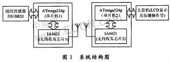
The designed wireless temperature sensor is mainly composed of the following components: temperature measurement, transmitting part, receiving part, LCD display part and control part. The system structure diagram is shown in Figure 1.
1.1 Temperature measurement circuit
The 1-Wire bus digital temperature sensor DS18B20 from Dallas is used in the temperature measurement circuit. The temperature measurement circuit is shown in Figure 2.
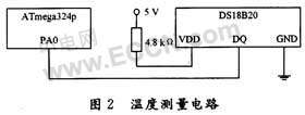
DS18B20 is a 3-pin TO-92 small package; temperature measurement range is -55 ~ 125 ° C, programmable 9-12 A / D conversion accuracy, temperature resolution up to 0.062 5 ° C, measured temperature to 16-bit digital serial output with sign extension.
The internal structure of the DS18B20 consists of four main components: a 64-bit ROM, a temperature sensor, a non-volatile temperature alarm trigger TH and TL, and a configuration register. The 64-bit serial number in the ROM is lithographed before leaving the factory. It can be regarded as the address sequence code of the DS18B20. The 64-bit serial number of each DS18B20 is different. The role of the ROM is to make each DS18B20 different, so that multiple DS181E0 can be connected to one bus.
The temperature sensor in the DS18B20 performs temperature measurement and is provided in a two's complement form with a 16-bit sign extension, expressed as 0.062 5°C/LSB. For example, the digital output of +25.062 5°C is 0191H, and the digital output of -25.062 5°C is FF6FH.
The high and low temperature alarm triggers TH and TL, the configuration registers are all composed of one byte of E2PROM, which can be written to the TH, TL or configuration registers using a memory function command. The format of the configuration register is as follows:

R1 and R0 determine the precision digits of temperature conversion: R1R0=“00â€, 9-bit precision, maximum conversion time is 93.75 ms; R1R0=“01â€, 10-bit precision, maximum conversion time is 187.5 ms; R1R0=“10†11-bit precision, maximum conversion time is 375 ms; R1R0; "11", 12-bit precision, maximum conversion time is 750 ms; default is 12-bit precision when not programmed. The design takes R1R0 = "11".
1.2 wireless transceiver circuit
1.2.1 Interface between IA4421 and MCU
IA4421 supports SPI communication protocol. This design selects ATmega324p, a high-performance single-chip microcomputer produced by American ATMEL Company. It has built-in enhanced SPI interface and 32 kB FLASH, which can display Chinese characters on the LCD in the system. The interface circuit diagram of IA4421 and MCU is shown as in Fig. 3.
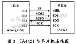
The ATmega324p's built-in enhanced serial peripheral interface SPI provides access to a full-duplex synchronous serial bus. The four signals used by the SPI are MOSI, MISO, SCK and SS. MOSI is used for serial data transfer from the master to the slave; MISO is used for serial data transfer from the device to the master; SCK is used to synchronize serial data between the master and slave on the MOSI and MISO lines transmission.
1.2.2 Wireless transmission timing
The transmission mode of IA4421 is the transmission mode of the transmission register buffer. It is enabled by the 7th el of the configuration setting command. As can be seen from Figure 1, the IA4421 has two 8-bit data registers, and the transmitted data is first latched into it. In a data register, when bit 5 of the power management command is set to 1, the transmitter begins to send data out of the first register at the set bit rate.
Each time data is sent, 0xAA must be used as the preamble of the transmitted data, otherwise the external receiving device cannot receive the data. If the synchronous mode is used, 0x2DD4 should be used as the signature of the synchronous mode before data can be transmitted. The pin nIRQ can be used to detect if the register is ready to receive the next byte from the microprocessor for transmission. If the pin nIRQ goes low, the register is ready.
1.2.3 Wireless Receive Timing
There are two ways to receive the IA4421: one is to receive all the time; the other is FIFO mode. The former method is not recommended and will cause a high bit error rate. This design uses the latter model. After the corresponding control word is set, the data has entered the buffer. If the pin nIRQ goes low, it indicates that the IA4421 is ready to receive data. At this time, the FIFO read command word is sent to start receiving.
1.3 Peripheral antenna design
The IA4421's support antenna is directly driven, and the design is quite simple and convenient, and the communication distance is long. A 50 Ω external spiral antenna and corresponding differential circuit enable data transmission and reception. The antenna designed by this system is realized by a single-core copper wire of 1.17 cm, the diameter of the wire is 0.6 mm, and the metal rod of the screwdriver is used to make 7 turns into a spiral shape. After the experiment, the actual effective communication distance can reach 200 m, which satisfies the system needs.
2 system software design
2.1 MCU software design
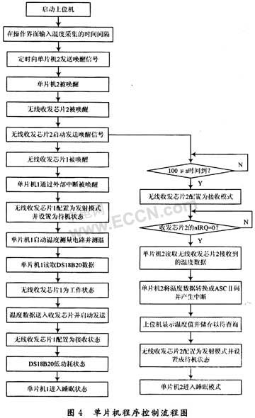
The software part of the MCU mainly includes main program, interrupt subroutine, temperature measurement subroutine, LCD conversion display, buzzer alarm subroutine, button subroutine and SPI subroutine. In order to reduce power consumption, interrupts are used to wake up the MCU for temperature measurement. Therefore, the main program part is relatively simple. It is mainly responsible for the initialization and interrupt calls of various parts of the system. After the system initialization is completed, it enters the sleep mode directly. When the interrupt arrives, the MCU will enter the sleep mode. Exit the sleep mode, call the interrupt subroutine to achieve temperature measurement, conversion display, temperature data transmission and other functions. The flow chart of the MCU control program is shown in Figure 4.
2.2 IA4421 application design
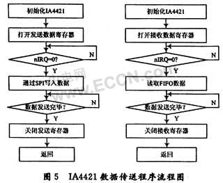
The system is based on the wireless serial transceiver IA4421 and the enhanced serial peripheral interface SPI of the ATmega324p to realize wireless data transmission, and write its own upper application on the core protocol stack. The program flow chart for sending and receiving data is shown in Figure 5.
2.3 Low power design
As a wireless sensor, low-power operation can maximize the effective use of the device. The system is powered by battery, and power consumption is definitely a problem that has to be considered. In order to achieve the best performance, the design must be weighed according to the situation in terms of power loss and availability. In addition to the low-power devices, the power management program is designed from the following aspects to minimize the power consumption of the wireless temperature sensor:
(1) Since the wireless temperature sensor is responsible for transmitting data to the control terminal, when to collect data and when to transmit data can be determined by the control terminal of the host computer, which is very suitable for using the sleep mode and the breathing mode, by reducing the IA4421 in the piconet. The activity in the middle reaches the goal of saving electricity. The control terminal is used as the master device, and the power management program is designed in the application control layer of the terminal, and the control terminal completes the query, pairing, and chain building of the device. When the wireless sensor and the control terminal are successfully paired and connected, the sleep mode is entered. At this time, the master and slave devices still maintain the channel, but cannot send and receive data. When data transmission is required, the sleep mode is exited into the breathing mode, and the data is sent through the breathing time slot. The breathing interval can be set to 20 to 40 ms, and the interval is too late to bring about a significant delay. When the data transmission ends, the sleep mode is entered again. Reduce energy consumption as much as possible.
(2) Applying the sleep mode of the single-chip microcomputer to achieve energy-saving purposes. When the IA4421 exits the standby state and sends a command for data acquisition, the interrupt request flag nIRQ of the IA4421 generates a low level, and an external interrupt is generated by the change of the level on the interrupt flag bit to wake up the microcontroller to enter the working state.
Description of Cable Management Sleeve For Wire Protection
Unique braided construction and wide expandability allows quick and easy installation over large connectors and long runs.
Ease of installation and nearly complete coverage makes fray resistance braided sleeve an ideal solution for many industrial and engineering applications.
The Cable Wire Sleeve has smooth surface, bright color and various patterns. It is an ideal product for line management and bundle application of electronics, automobiles, airplanes, ships, industry and home. For example, DVI wire mesh sets, HDMI wire net sets, motor vehicle engine line dressing, home theater wire management, computer chassis wire layout, office line management, car wiring harness, water tube protection.
Pet Expandable Braided Sleeve for cable harness is braided by environment-friendly polyester monofil. (PET,PA66), the sleeve possesses good flexibility, fire resistance, abrasive resistance and thermal insulation performance. The sleeving owns smooth surface, bright color, various patterns.
Cable Management Sleeve
Expandable Braided Cable Sleeve,Nylon Wrap Around Cable Sleeve ,Pipe Cable Sleeves,Braided Cable Sleeve
Shenzhen Huiyunhai Tech.Co.,Ltd , https://www.hyhbraidedsleeve.com