Some time ago, I helped a friend fix a number of elevator electronic boards, including the door control board, code board, I/O board, main control board, inter-floor communication board, and display board. It was a bit smaller in size, but I thought it would be useful to share some of my experience with you.
Elevator electronic boards are typically divided into several functional modules. Here's a general breakdown:
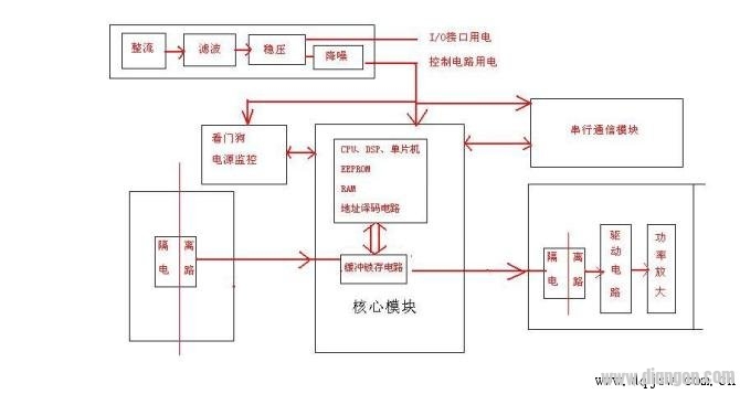
1. **Power Module**: This usually includes a rectifier circuit, voltage stabilization circuit, filter circuit, and power monitoring circuit. These components ensure that the board receives stable and safe power.
2. **Core Processing Module**: This is the brain of the board and includes components like the CPU (or microcontroller/DSP), EEPROM, RAM, address decoding circuits, oscillator, reset circuit, and watchdog circuit.
3. **Signal Input Module**: This handles incoming signals from sensors or other devices. It often includes a buck circuit, signal isolation (using optocouplers or micro-transformers), and buffer latch circuits.
4. **Signal Output Module**: This sends signals to actuators or displays. It includes buffer latches, isolation circuits, and power amplifier circuits to drive external devices.
5. **Serial Communication Module**: Common communication protocols in elevators include RS232, RS485, and CAN bus. RS232 is used for connecting to debuggers or computers, while internal communication usually uses RS485 or CAN bus.
Under normal operation, the core components such as the processor, EPROM, RAM, and crystal oscillator are relatively robust. They operate at low voltages (usually 5V or lower) and use binary signals, making them less prone to failure. Most issues occur in the I/O interface and power supply sections. For example, problems can arise in input resistors, output transistors, thyristors, or driver circuits. Power-related faults may include no voltage, low voltage, or unstable fluctuations.
Before starting repairs, it’s important to understand the symptoms and the function of each interface. This helps in quickly identifying the root cause. When working on these boards, always be cautious and avoid shorting unknown signals, as this can lead to further damage.
In my experience, the typical repair process involves the following steps:
1. **Initial Check**: First, verify if the board initializes properly. Look for signs like relay activation, LED display, or error messages. If there’s an alarm or display, the core module is likely functioning.
If not, check the external power input and current. Once power is confirmed, test the CPU voltage (usually 5V), reset circuit, and oscillator.
A common issue I’ve encountered is a faulty reset circuit caused by low core voltage. The core voltage refers to the stabilized voltage after passing through the rectifier, regulator, and filter circuits. It should be above 4.6V for the CPU and 5V for the watchdog circuit.
2. **No Signal Response After Input**: Confirm that the power is stable and the CPU is working. Then check the input circuit, including protection diodes, current-limiting resistors, and isolation transformers. Use an optocoupler as a test point to determine if the fault is on the input or output side.
You can apply a known voltage to the input side and see if the board responds. If it does, the problem is in the front-end circuit. If not, connect a 5V source through a 470Ω resistor to the output side and test again.
3. **No Output Signal**: Again, start by confirming power and CPU functionality. Check the input signal and then move to the output interface. Test the power amplifier, driver circuit, isolation components, and latch circuits.
4. **Communication Issues**: Communication errors can sometimes disrupt the entire network, even though they may originate from a single node. In one case, an elevator had erratic behavior—doors wouldn’t close, and the display showed errors. After checking, we found a faulty external call board and replaced capacitors, which resolved the issue.
While I have gained a lot of hands-on experience, I still have more to learn, especially regarding advanced technologies like CAN bus. Feel free to ask questions or share your own experiences—I'm always eager to learn and improve.
Power Supply for Industrial Equipment,industrial power supply 24v,1200W Power Supply Adapter
FOSHAN SHUNDE KELICHENG POWER SUPPLY TECHNOLOGY CO., LTD , https://www.kelicpower.com