Some time ago, I helped a friend repair several elevator electronic boards, including the door control board, code board, I/O board, main control board, intercom communication board, and display board. The project was a bit smaller in scale, but I thought it would be useful to share my experience with you.
Elevator electronic boards typically consist of several key modules:
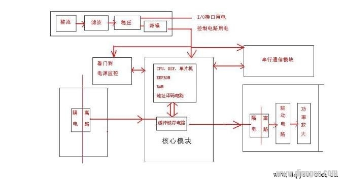
1. **Power Module**: This usually includes a rectifier circuit, voltage regulation circuit, filter circuit, and power monitoring circuit. It ensures stable power delivery to the rest of the system.
2. **Core Processing Module**: This contains the CPU or microcontroller, EEPROM, RAM, address decoding circuits, oscillator, reset circuit, and watchdog circuit. These components are responsible for processing and managing the elevator's operations.
3. **Signal Input Module**: This handles incoming signals from sensors and switches. It includes a voltage divider, signal isolation (often using optocouplers or micro-transformers), and buffer latch circuits.
4. **Signal Output Module**: This sends signals to actuators and other components. It also uses buffer latches, isolation circuits, and power amplifier circuits to drive outputs effectively.
5. **Serial Communication Module**: Commonly uses RS232, RS485, or CAN bus for internal and external communication. RS232 is often used for connecting to a computer or debugger, while RS485 or CAN bus is used for internal communication between boards.
Under normal operation, the core components—like the processor, EPROM, RAM, and crystal oscillator—are rarely damaged. They operate at low voltages (typically 5V or less) and handle binary signals, making them relatively robust. Most faults occur in the I/O interface and power supply sections. For example, issues may arise in the input protection resistors, output transistors, thyristors, or driver circuits. Power-related problems often include no voltage, low voltage, or excessive fluctuations.
Before starting repairs, it's crucial to gather detailed information about the fault. Understanding the function of each interface helps narrow down the problem quickly. Always proceed carefully when working on the board. If unsure about a signal, avoid shorting it to prevent further damage.
In my experience, the typical repair process involves the following steps:
1. **Initial Check**: First, verify if the board initializes properly. Look for signs like relay activation, LED display, or error messages. If there’s an alarm or display, it usually indicates that the core module is functioning.
If not, check the input voltage and current. Ensure the power supply is stable, then test the CPU voltage (usually 5V), reset circuit, and oscillator. A common issue is a faulty reset circuit, often caused by unstable core voltage due to a weak power supply or a malfunctioning watchdog circuit.
2. **No Signal Response After Input**: Confirm that the power is normal and the CPU is working. Then inspect the input circuit, checking for blown protection diodes, current-limiting resistors, and the integrity of isolation transformers or optocouplers. Use the optocoupler as a reference point to determine if the fault lies before or after it.
To test, apply a known voltage to the input side of the optocoupler and see if the board responds. If it does, the issue is likely in the front-end circuit. If not, try applying a 5V signal through a 470-ohm resistor to the output side and check again.
3. **No Output Signal**: Start by confirming the power supply and CPU functionality. Then check the input signal and work your way through the output circuits, including the power amplifier, driver circuits, and isolation components.
4. **Communication Issues**: Communication errors can sometimes disrupt the entire network, even if only one node is faulty. For example, during a recent repair, an elevator had intermittent door-opening issues. After replacing capacitors and checking all communication boards, the problem was resolved. While I don’t have extensive knowledge of CAN bus technology, these hands-on experiences have been invaluable.
Due to the complexity of these systems and my own limitations, I encourage others to double-check their findings and consult more advanced resources when needed. Every repair is a learning opportunity, and sharing experiences helps us all grow.
waterproof ac adapter,waterproof 12v dc power supply,water clarifier power adapter,Waterproof power supply
FOSHAN SHUNDE KELICHENG POWER SUPPLY TECHNOLOGY CO., LTD , https://www.kelicpower.com