Applications for FPGA SERDES need to take into account board-level hardware, SERDES parameters and usage, application protocols, and more. Due to this complexity, the debugging of SERDES is a challenge for many engineers. This article will describe the general debugging method of SERDES, which is convenient for engineers to locate and solve problems accurately and quickly.
Hardware detection
Hardware detection can be divided into schematic/PCB inspection and on-board hardware inspection. This part of the work is relatively simple, but in many cases the problem is caused by these seemingly inconspicuous places.
a) Schematic / PCB inspection
Check the schematic and PCB design according to the requirements of the SERDES application manual. For example, for the Xilinx 7 Series GTX/GTH SERDES, check the schematic and PCB design for the UG476 Board Design Guidelines.
b) Onboard hardware check
Use an instrument such as an oscilloscope/multimeter to actually measure the on-board hardware and verify that the working environment provided to the SERDES is normal.
i. Check that the voltage/precision/ripple/power-up sequence of the power supply meets the requirements of the data sheet. For example, for the Xilinx 7 Series GTX SERDES, check with the DS182.
Ii. Check that the SERDES reference clock frequency/swing is in compliance with the data sheet and that the reference clock pin is in the correct position.
Iii. Check the physical channel, for example, confirm that the capacitance of the AC coupling capacitor is correct, whether the optical module is compatible, and whether the soldering is normal.
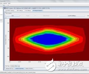
2. Using IBERT
IBERT is a powerful debugging tool that can be used to adjust parameter settings and confirm system margins, as well as for fault symptom determination. IBERT generates engineering and BIT files in the CORE generator. After downloading the BIT file to the FPGA and connecting to the FPGA using ChipScope Analyzer, the IBERT GUI debugging interface will appear.

a) Check if the PLL is LOCK. If not, check the clock and power. For example, if the clock frequency is correct, whether the SERDES selects the correct clock source.
b) Set the TX and RX of the SERDES to the same data pattern, such as PRBS-31. Set SERDES to Near-end PMA mode. If this step does not work, check if the TX/RX polarity is reversed; check if the clock frequency on TXUSRCLK/TXUSRCLK2/RXUSRCLK/RXUSRCLK2 is normal. This step ensures that the SERDES works properly inside.
c) Set the SERDES to Far-end PMA and Far-end PCS mode to confirm that the SERDES of the remote device is transmitting and receiving normally. This step eliminates the problems associated with the clock OFFSET.
d) If these steps work fine, but the bit error rate is high, there may be a problem with the parameter settings. Need to be solved by adjusting the TX/RX parameter settings. The EYE SCAN function can also be used to get the best settings and to determine the system margin.
Features and Benefits of Surge Suppression Filters:
Have both surge and fltering function.
Surge class conforms to GB/T 17626.5-2008 / IEC61000-4-5:2005 Standard.
FTSF1 series filter is common AC filter, which is designed with one-stage common mode filter circuit.
The surge suppresion devices have good filtering effect and the effective filter range is 150kHz ~ 30MHz.
Compact structure,cost-effective, safe, convenient, and more reliable.

Surge Suppression Filters
Surge Suppression Devices,Surge Suppression Filters,Surge Suppression Emi Filters,Emc Filter
Jinan Filtemc Electronic Equipment Co., Ltd. , https://www.chinaemifilter.com