However, you must note that the original design of the software was designed to provide minimal compatibility with the "snapshot" technology, rather than providing a complete compatibility tool for PCI Express. The full compatibility specification requires the manufacturer to measure and report a total of 30 parameters that are consistent with the PCI Express Version 1.1 base specification and the board's electromechanical specification (References 1 and 2), while the SIG software only needs to measure and report 4 parameters ( VTXA, VTXA_d, TTXA, TTXA-MEDIAN-to-MAX-JITTER). Table 1 and Table 2 give the output specification of the differential transmitter and the input specification of the differential receiver, respectively. In addition, the phase jitter of the reference clock peak/peak cannot exceed 86ps under BER=6~10, and does not exceed 108ps when BER=10~12.
The PCI SIG software can be used for customer authentication, but the more powerful commercial compatibility test packages available from various vendors can provide a more comprehensive list of parameters required by the PCI Express specification. You can use these commercial test kits to design products that not only meet the specification requirements, but also have a higher design margin and better quality.
When evaluating commercial test packages, you need to compare the performance of different test packages against the PCI Express specification until you find a test package that suits your testing needs. You can also spend some time to understand the basic measurement methods for each test package, and these basic measurements can all be in parameters [such as jitter, noise, and bit error rate (BER), also known as JNB] Other relevant results were obtained in the test.
The best test methods, the best test instruments, and the best software packages are used to make the most direct measurements of your product-related parameters. You may need to use some instruments and methods for testing, and each instrument and method can provide the best solution for testing the parameters that need to be measured and reported.
The use of appropriate compatibility tools is not intended to give the product a certain "nice to have" performance, but rather to the important issue of maintaining market competitiveness. The limited design margin of components can lead to serious business problems. Such components may pass the minimum compatibility test, but if a failure occurs in the later use process, it will definitely affect the profit of the product's production line or business entity.
Failure analysis
When a component fails or is recalled on the production line, you can also use the PCI Express Compatibility Tool to perform failure analysis. Because by definition, the compatibility tool can test its design after the component is completed. However, many test packages can only provide limited or no diagnostic tools to help developers find errors caused by invalid parameters. If you use a tool with failure analysis, you can find the source of the problem and quickly find a solution. The quick solution will improve the satisfaction of the users and increase the market sales of the products.
Robust packages provide dynamic diagnostic tools for clocks and data. Without first verifying the accuracy of the clock signal, relatively small errors can develop into serious errors.
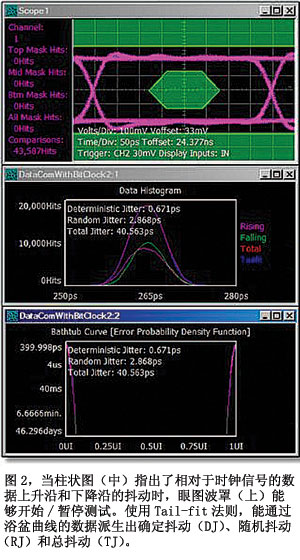
Here, several examples of diagnosis are given from different details. Figure 1 shows the different test results for a PCI Express data signal using a compatible clock and no compatibility clock. Figure 2 shows an eye diagram, a dithered bar chart, and a bathtub measurement curve for the PRBS 223-1 mode. Wavecrest's TailFit algorithm (References 3 and 4) is applied to the jitter histogram. Random jitter (RJ) and deterministic jitter (DJ) can be generated in 1 second by measuring the signal from the pattern pattern generator. And total jitter (TJ) results.
Another function enables the PCI Express compatibility test to find function values, including using different forms of jitter characterization, such as the Fast Fourier Transform (FFT). In addition, the clock/phase-locked loop (PLL) tool can isolate the wrong reference clock or the serializer (Serdes) problem caused by the PLL.
The last example demonstrates the importance of diagnostic tools. Taking into account that the test results will be used for transmitters compliant with the PCI Express standard, Figure 3 describes the signal/jitter output of the transmitter for a full-swing eye (Figure 3a) and a de-emphasis eye diagram ( De-emphasis eye) (Figure 3b) and the BER Cumulative Distribution Function (CDF) and the associated total jitter (associated TJ) under BER=10~12 (Figure 3c).
In the figure, the measured degree of eye opening is 0.649 unit intervals (UI) (or TJ=61.2 ps). The test specification states that the sender has a minimum eye opening of 0.75 unit intervals (UI), so this PCI sender invalidates the compatibility test on the edge.
Figure 4 shows the data-dependent jitter (DDJ) distribution of the same transmitter, the power spectral density (PSD) of periodic jitter (PJ) and random jitter (RJ). The transmitter dither output diagnostic test results take the measurement DDJ as a function of the unit interval (UI) range. The DDJ histograms are labeled with a rising edge (green) and a falling edge (pink). The picture at the bottom left is an enlarged view of the worst point of the DDJ. The plot at the lower right is a plot of PJ and RJ power spectral density (PSD).
These diagnostic views provide important information for detecting major jitter signals. For example, a 5MHz signal with 20.9ps periodic jitter is not easily noticeable. This periodic jitter needs to be identified or eliminated early in the development cycle, so the transmitter needs to pass a high design margin compatibility test. In another case, DDJ is 20.76ps, and RJ is 1.4ps, then both factors can be considered as non-main factors.
Once you have selected the software package for PCI Express compliance testing, you can use the same instrument and test method throughout the product cycle. This will allow for an uninterrupted transition from feature design to high-volume production. This approach saves time, reduces testing costs, and can shorten the time-to-market for your company. Using the same test method in all cases can eliminate the confusion of different measurement values ​​brought about by various test methods and platforms.
references:
1. "PCIe Base Specification 1.1," PCI SIG, 2005.
2. "PCIe Card Electromechanical Specification 1.1," PCI SIG, 2005,
3. "Signal-Integrity Analysis Tool Targets PCI Express and SATA II," Test & Measurement World Online, August 12, 2005.
4. Nelson, Rick, "Serdes devices challenge ATE," Test & Measurement World, August 2002.
Sex Toy Vibration Motor voltage is lower than 6 v, small size, shaking force is strong, the price is cheap. Concrete can be customized according to the requirements of various parameters of the Vibration Motor!
Copper
tungsten steel material
plate material


Vibration of the motor head material, copper, tungsten steel material, plate material, place head motor with different material, different vibration strength, the unit price is different
Operating temperature range:
Sex Toy Vibration Motor should be used at a temperature of -10~60℃.
The figures stated in the catalog specifications are based on use at ordinary room temperature catalog specifications re based on use at ordinary room temperature (approximately20~25℃.
If a Micro Vibration Motor For Sex Toy is used outside the prescribed temperature range,the grease on the gearhead area will become unable to function normally and the motor will become unable to start.Depending on the temperature conditions ,it may be possible to deal with them by changing the grease of the motor's parts.Please feel free to consult with us about this.
Storage temperature range:
Sex Toy Vibration Motor should be stored ta a temperature of -15~65℃.
In case of storage outside this range,the grease on the gearhead area will become unable to function normally and the motor will become unable to start.
Service life:
The longevity of Micro Vibration Motor For Sex Toy is greatly affected by the load conditions , the mode of operation,the environment of use ,etc.Therefore,it is necessary to check the conditions under which the product will actually be used .The following conditions will have a negative effect on longevity.Please consult with us should any of them apply.
â—Use with a load that exceeds the rated torque
â—Frequent starting
â—Momentary reversals of turning direction
â—Impact loads
â—Long-term continuous operation
â—Forced turning using the output shaft
â—Use in which the permitted overhang load or the permitted thrust load is exceeded
â—A pulse drive ,e.g.,a short break,counter electromotive force,PWM control
â—Use of a voltage that is nonstandard as regards the rated voltage
â—Use outside the prescribed temperature or relative-humidity range,or in a special environment.
â—Please consult with us about these or any other conditions of use that may apply,so that we can be sure that you select the most appropriate model.
when it come to volume production,we're a major player as well .each month,we rurn out 600000 units,all of which are compliant with the rohs directive.Have any questions or special needed, please contact us, we have the engineer group and best sales department to service to you Looking forward to your inquiry. Welcome to our factory.

Sex Toy Vibration Motor
Sex Toy Vibration Motor,Micro Vibration Motor For Sex Toy,Dc Sex Toy Vibration Motor,12V Motor For Sex Toy Vibrator
Shenzhen Shunchang Motor Co., LTD. , https://www.scgearmotor.com