With the increasing living standards of people, the aging of China's population is becoming more and more obvious. As a kind of service robot, vacuuming robots can replace people to clean some simple labor such as rooms, workshops and walls.
Making service robots have a broad market has become the focus of research by some enterprises and research institutes. At present, the vacuuming robots on the market are also intelligent, but most of them are costly due to unreasonable structure, poor versatility, and high integration, which is not conducive to popularization. Based on the research and summary of relatively mature products on the market, an indoor vacuuming robot with self-navigation function is designed based on ARM Cortex-M3 processor. The utility model has the advantages of compact shape, simple structure, stable operation, low noise, low cost, convenient operation, and an expandable interface, and the user can further develop its function according to actual needs.
1. The overall composition of the vacuuming robot
Designing a mobile cleaning robot for indoor use with the ARM Cortex-M3 processor, the main task is to be able to clean the room by itself, so it should have the following functions:
(1) can correctly judge the room in which the robot is located and the position in the room;
(2) It can correctly detect obstacles such as walls and furniture in the room;
(3) After completing the cleaning task in all rooms, you can return to the starting point and shut down.
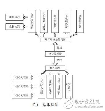
In order to prevent the robot from stalling during work, and to freely enter some furniture such as sofas, tables, etc., the vacuuming robot can not be too high, and the shape is semi-cylindrical. The chassis is supported by four wheels, wherein the left and right sides are driving wheels, which are directly driven by two micro DC motors, and the front and rear two universal wheels serve as support and guide. Multi-sensor system is composed of collision, infrared sensor and ultrasonic. An infrared receiving sensor is arranged above the robot, and a proximity sensor is evenly distributed on the edge of the chassis for detecting obstacles; a collision sensor is installed in front of the robot; and an ultrasonic distance measuring sensor is arranged on the front and the left side to detect the surrounding environment.
The overall frame design is shown in Figure 1.
2, hardware design
The hardware system is mainly composed of ARM Cortex-M3 processor, sensor module, motor drive module, human-computer interaction module and wireless remote control transmitter module.
2.1 ARM Cortex-M3 processing
The main task of the robot control system is to perform cleaning route planning, control cleaning and vacuuming mechanisms, and complete various control actions based on the feedback data from sensors and encoders. Design a suitable human-machine interface to display the robot status and running time on the LCD. Therefore, the robot control system includes a sensor module, a motor drive module, an infrared remote control receiving module, an LED indicator light, and a liquid crystal display module. The ARM Cortex-M3 processor is used as the core of the robot control system, which is mainly low cost, small pin count and low power consumption, and has extremely high computing power and strong interrupt response capability, and the operating current is only 50 mA.
2.2 Motor Module
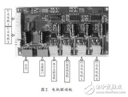
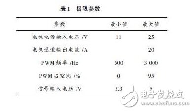
Divided into small motor drive circuit and two high-power drive boards, including two small DC motors for walking and high-power brushless DC motors for vacuuming, DC brush motors for sweeping, DC side brushes for sweeping corners Motor. Because the motor determines the walking path and vacuuming power of the robot, a special drive board is designed, as shown in Figure 2. The design of the walking module plays a vital role in the obstacle avoidance planning of the vacuuming robot. We design the vacuuming robot as a closed loop control, which mainly includes the driving circuit and the photoelectric encoding feedback circuit. The photoelectric code feedback circuit obtains the current motor speed by calculating the number and phase of the feedback feedback. The chip can drive a motor of up to 25 V. The working voltage of the walking motor in the vacuuming robot is 24 V, and the voltage of the chip is 5 V. The PWM wave output from the chip is converted into a large voltage PWM wave control motor. The limit parameters are shown in Table 1.
2.3 sensor module
It mainly consists of 3 parts: ultrasonic module for measuring and sensing obstacles, infrared and collision sensors, sensors for state detection (detecting battery power, dust bucket, motor stalling and floating). The sensor module allows the robot to make the right judgments about the surrounding environment and provide intelligent decisions for the successful completion of tasks.
(1) Ultrasonic ranging sensor module
Due to the working environment, indoor vacuuming robots must have obstacles for detecting various sizes, heights, and colors. Ultrasonic is a non-contact detection technology that spreads in the air without external factors such as light, smoke, and electromagnetic fields. Interference, compared with infrared sensors, ultrasonic sensors have longer sensing distances, higher reliability, and lower cost. Therefore, the detection of obstacles can be effectively performed using a high-precision ultrasonic ranging system.
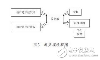
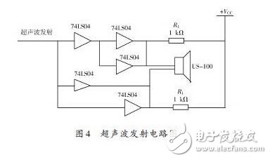
In this paper, the US-100 ultrasonic ranging module can realize non-contact ranging function of 0~4.5 m, with a wide voltage input range of 2.4~5.5 V, static power consumption less than 2 mA, and its own temperature sensor for ranging. The result is corrected, and has various communication modes such as GPIO and serial port, and the work is stable and reliable. Two ultrasonic sensors are installed in front of and behind the robot. The processor generates a 40 kHz pulse through the I/O port output, and then passes through the NAND gate and the triode to amplify two pulses of opposite polarity input to the ultrasonic transmitter. The probe can emit a series of ultrasonic waves of 40 kHz, return to the receiving circuit after encountering obstacles, and the processor simultaneously controls the gate circuit to realize the discontinuity of the transmitted wave as shown in FIG. The ultrasonic receiving end converts the signal reflected back by the obstacle into an electrical signal through low-noise amplification and band-pass filtering, and then compares the interrupt to the processor for time measurement, thereby making the distance judgment of the obstacle. ,As shown in Figure 4.
(2) Infrared and collision sensor modules
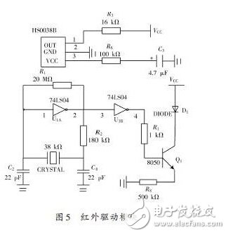
The vacuuming robot mainly uses ultrasonic ranging for long-distance obstacles during work, but the ultrasonic wave is not sensitive to short-distance obstacles, so an infrared module is added for close-range detection, and an infrared measuring module is designed according to the energy reflection method. Two sets of infrared sensors are installed in front of and behind the robot. Each group consists of up to 14 sets of infrared transmitting and receiving tubes. There are 14 upper and lower chassis mounted on the robot. Each of the upper and lower infrared transmitting and receiving tubes is connected in parallel and points in the same direction. Form a group, each group of circuits can be divided into high-frequency pulse signal generation, infrared emission adjustment and control, infrared emission drive, infrared reception and other parts. A 38 kHz modulated pulse signal is obtained through a 38 kHz crystal and NAND circuit; the emission of the infrared transmitting tube (TSAL6200) is driven by a triode. The infrared light emitted by the launch tube is reflected by the object and received by the infrared receiving module. After being processed by the integrated circuit inside the receiving head (HS0038B), it returns a digital signal and inputs it to the I/O port of the microcontroller, as shown in Figure 5. Show.
The receiver will return to the output low level if it receives an infrared pulse of 38 kHz, otherwise it will output a high level. By detecting the I/O port, it is possible to judge the presence or absence of an object. In this way, a total of 14 directions can be detected, covering the 360° range. The robot can detect the short-distance obstacles in front and rear, and can work in both forward and backward directions. The effective distance of the obstacle-detecting sensor composed of two infrared receiving tubes is close to 2 m, and it can also be within the range of the ball very close (10 cm). ) Read obstacle distance results (no overflow).
Four collision switches (normally open) are installed in the left front, left rear, right front and right rear of the robot. By collecting the change of the voltage value on the analog port, it is judged that one or several of the collision switches are closed, thereby detecting which one There is a collision in the direction.
2.4 Human Computer Interaction Module
(1) Liquid crystal display and keyboard input: The two can be used together to set various parameters of the robot, such as self-starting and setting working time.
(2) Wireless remote control module: The infrared remote control makes the use of the robot more convenient and simple, and the launching distance exceeds 10 m, which can meet the needs.
3, the conclusion
Through such a hardware design, the cleaning robot control system can not only satisfy the good practicability, but also reduce the cost and work stably and reliably. The robot sensor module can accurately locate obstacles and achieve good obstacle avoidance through software strategy. It has important practical significance for the research and development of home service robots in the future.
KNL4-100 Moulded Case Circuit Breaker is MCCB , How to select good Molded Case Circuit Breaker suppliers? Korlen electric is your first choice. All moulded Case Circuit Breakers pass the CE.CB.SEMKO.SIRIM etc. Certificates.
Moulded Case Circuit Breaker /MCCB can be used to distribute electric power and protect power equipment against overload and short-current, and can change the circuit and start motor infrequently. The application of Moulded Case Circuit Breaker /MCCB is industrial.
Korlen electric also provide Miniature Circuit Breaker / MCB . Residual Current Circuit Breaker /RCCB. RCBO . Led light and so on .
KNL4-100 Residual Current Circuit Breaker
KNL4-100 Molded Case Circuit Breaker,KNL4-100 Small Size Molded Case Circuit Breaker,KNL4-100 Electrical Molded Case Circuit Breaker,KNL4-100 Automatic Molded Case Circuit Breaker
Wenzhou Korlen Electric Appliances Co., Ltd. , https://www.korlenelectric.com