Industrial motion control covers a range of applications, including inverter-based fan or pump control, factory automation with more complex AC drive control, and advanced automation applications such as robots with advanced servo control. These systems need to detect and feed back multiple variables such as motor winding current or voltage, DC link current or voltage, rotor position and speed. Among considerations such as value-added functions (such as condition monitoring), the terminal application requirements, system architecture, target system cost, or system complexity will determine the choice of variables and the required measurement accuracy. According to reports, motors account for 40% of the total global energy consumption, and international regulations are increasingly focusing on the system efficiency of industrial motion applications. Therefore, these variables are becoming more and more important, especially current and voltage.
This article will focus on current and voltage sensing in various motor control signal chain topologies based on motor rated power, system performance requirements, and end applications. In this case, the implementation of the motor control signal chain will vary depending on sensor selection, galvanic isolation requirements, analog-to-digital converter (ADC) selection, system integration, and system power and ground division.
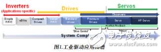
Industrial driver application map
From simple inverters to complex servo drives, motor control applications cover a range of motor types, but all motors include motor control systems with specific power levels, as well as different levels of detection and feedback to drive pulse width modulators ( The processor of the PWM) module. Figure 1 is a simplified diagram of the application map showing various systems with increasing complexity from left to right, starting with a simple control system, such as pumps, fans, and compression that can be implemented using a simple microprocessor without precision feedback. machine. As system complexity increases (ie, shifts to the higher end of the spectrum), complex control systems require precise feedback and high-speed communication interfaces. For example, vector controlled induction motors or permanent magnet motors with or without sensors, and high power industrial drives (such as large pumps, fans, and compressors) designed for the efficiency shown in Figure 1. At the very end of the spectrum are complex servo drives for applications such as robots, machine tools and placement machines. As system complexity increases, the detection and feedback of variables becomes more critical.
Drive architecture system partition
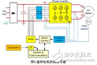
We may encounter various problems when designing systems that meet the needs of various industrial motion control applications. The general motor control signal chain is shown in Figure 2.
Isolation requirements are very important and often have a significant impact on the resulting circuit topology and architecture. There are two key factors to consider: the cause and location of the isolation.
The requirements for quarantine classification depend on the former. High voltage safety isolation (SELV) may be required to protect against electric shock, or functional isolation for level shifting between non-fatal voltages, or isolation for data integrity and noise reduction. The isolation location is usually determined by the expected performance of the system. Motor control is typically performed in harsh environments with electrical noise, and designs typically withstand common-mode voltages of hundreds of volts, may switch at frequencies above 20 kHz, and have extremely high transient dv/dt rises. time. For this reason, higher performance systems and high power systems with higher inherent noise are typically designed to have a power level that is isolated from the control stage. Whether it is a single processor or a dual processor design will affect the isolation location. In low-power systems with lower performance, isolation is usually done on the digital communication interface, which means that the power stage and the control stage are at the same potential. The communication interface that needs to be isolated in the low-end system has a lower bandwidth. Because high-end systems require high bandwidth and traditional isolation techniques have limitations, it is often difficult to isolate the communication ports of high-end systems. But with the advent of magnetically isolated CAN and RS-485 transceiver products (such as those from Analog Devices, Inc.), the situation is changing.
In high-performance closed-loop motor control design, two key components are composed of PWM modulator output and motor phase current feedback. Figures 3a and 3b show the locations where safety isolation is required, depending on whether the control stage shares the same potential as the power stage or ground. In either case, the high-side gate driver and the current-sense node need to be isolated, but the isolation levels in Figure 3a are different. These nodes only need to be functionally isolated. In Figure 3b, the safety of these nodes is safely isolated (ie, galvanically isolated). ) is crucial.
Measurement techniques and topologies for current and voltage sensing
In addition to the system power and ground divisions described above, the signal chain implemented to detect current and voltage will vary depending on sensor selection, galvanic isolation requirements, ADC selection, and system integration. Signal conditioning for high fidelity measurements is not an easy task. For example, recovering small signals or transmitting digital signals in such a noisy environment is very challenging, and isolating analog signals is a greater challenge. In many cases, signal isolation circuits can cause phase delays that limit system dynamic performance. Phase current sensing is particularly difficult because the node connected to the node is the same as the node of the gate driver output in the power stage (inverter module) core, so the need for isolated power and switching transients is the same. The measurement signal chain (technology, signal conditioning, and ADC) that needs to be implemented in the motor control system is typically determined based on three key factors:
1. Determine the point or node in the system that measures the demand.
2. Motor power level and the final selected sensor (whether it has isolation). Sensor selection greatly influences the choice of ADC, including converter architecture, functionality, and analog input range.
3 terminal application. This can drive the need for high resolution, accuracy or speed in the detection signal chain. For example, implementing control without sensors over a large speed range requires more, more frequent, and more accurate measurements. End applications also affect the requirements for ADC functionality. For example, multi-axis control may require an ADC with a higher number of channels.
----------------------
How to easily overcome the quality problems of 4G product design? LTE test helps you!
   
Valve Regulated Lead Acid Battery
Valve Regulated Lead Acid Battery,Lead Acid Battery,Vrla Battery,12V 200Ah Lead Acid Battery
Henan Xintaihang Power Source Co.,Ltd , https://www.taihangbattery.com