Abstract: Design a wireless transceiver system based on PLL and TDA7010T. The system is composed of 3 parts: transmitting circuit, receiving circuit and control circuit. The transmitting circuit adopts FM and FSK modulation methods, and uses a phase-locked loop (PLL) to stabilize the planting frequency to realize the transmission of analog voice signals and English short messages. The receiving circuit takes the TDA7010T integrated device as the core, the peripheral circuit is simple, and the work is stable and reliable. The control circuit consists of a single-chip microcomputer AT89S51, an encoder PT2262, and a decoder PT2272, which composes and displays English short messages.
The wireless transceiver system is widely used in engineering, and a wireless transceiver system based on PLL and TDA7010T is designed. The transmitting circuit adopts PLL frequency synthesizer technology, the output carrier is 33.984 MHz, the stability reaches 4xlO-5, the accuracy reaches 3 × 10⁻⁵, the receiving circuit uses TDA7010T integrated device, and its monolithic monophonic portable frequency modulation An important part of the radio integrated circuit, with a frequency-locked loop (FLL) system, 70 kHz low and intermediate frequency makes the system work stable and reliable. The receiving frequency can be selected by adjusting the size of the resonant tank capacitor, and the peripheral circuit is extremely simple.
1 Overall system design
The system consists of a transmitting circuit, a receiving circuit and a control circuit. The transmitting circuit modulates the digital signal from the microphone analog signal or the control circuit by a phase-locked loop (PLL) modulation circuit, and then transmits it through the antenna; the receiving circuit receives and demodulates the small signal from the antenna and sends it to the final power amplifier for amplification Then, the voice signal is sent to the speaker for processing, and the short message is sent to the single-chip processor for processing; the control circuit is composed of the minimum system of the single-chip computer and the codec, which can realize the writing and display of English short interest. The entire system is powered by 5 V.
2 Hardware circuit design
2. 1 launching circuit design
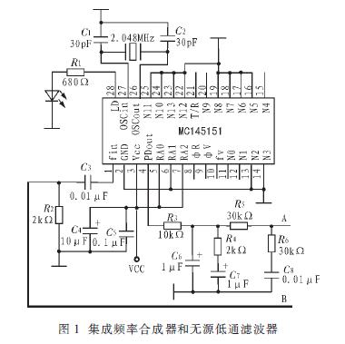
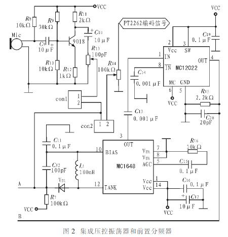
The design of the transmitting circuit is shown in Figure 1 and Figure 2, which consists of an integrated frequency synthesizer MCl45151, a passive low-pass filter, an integrated voltage-controlled oscillator MCl648 and a prescaler MCl2022. Among them, MCl648 needs an external resonant circuit composed of an inductor and a varactor diode to change the size of R7 to ensure that the voltage at point A of the varactor diode is between 1.5 and 3.5 V to make the MCl648 enter the locked state. The signal output from pin 3 of MCl648 is divided by the prescaler MCl2022. There are 4 types of frequency division coefficients. In this circuit, the frequency division ratio M = 64 is selected. The frequency-divided signal is sent to the MCl4515l, which has an R frequency divider and an N frequency divider, and divides the reference signal fx and the input signal fi of the crystal oscillator respectively. The frequency-divided 2-way signal is sent to the internal phase detector, and the output signal of the phase detector is filtered by an external low-pass filter to control the voltage-controlled oscillator. After the loop is locked, the following basic relationship is satisfied: 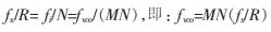
RA0, RAl, RA2 of MCl4515l are set to "1", "0", "1", namely R = 2 048, select fx = 2.048 MHz crystal oscillator, it can be calculated that every time the N value of the DIP switch increases 1. The frequency step of the voltage controlled oscillator is 64 kHz. For example, if N = (531) D = (00001000010011) B, M = 64, fx = 2.048 MHz, and R = 2 048, then fvco = 33.984MHz. Select the value of N through the DIP switch to set the carrier frequency.
The voice signal collected by the microphone is amplified by the triode amplifier with 9018 as the core and sent to the jumper end conl. After encoding, the SMS digital signal is sent to con2. The voice signal or English short message is sent by selecting the connection and disconnection of conl and con2. And can transmit any selected signal of l way to point A. When the signal voltage at point A changes, the junction capacitance of the varactor changes, causing the instantaneous frequency of the voltage-controlled oscillator to change, thereby achieving frequency modulation.
2. 2 receiving circuit design
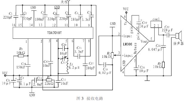
Figure 3 shows the receiving circuit. Adopt special frequency demodulation device TDA7010T, with FLL (Frequency Locked Loop) system, 70 kHz low and intermediate frequency makes the system work stable and reliable, and a voltage controlled oscillator is integrated inside. Connect appropriate capacitance and inductance between pins 4 and 5 of the device to determine the local oscillator frequency). Because the transmission carrier fc = "33". 984 MHz, so the local oscillator frequency fL = fc + 70 kHz = "34". 054 MHz, choose Ll = O. 2μH, the local oscillation loop tuning capacitance C = 110 pF, the actual selection of 80 pF capacitance and 20 pF / 40 pF variable capacitor in parallel. When receiving a signal, simply adjust the value of the variable capacitor C15 of the resonant circuit to select the receiving frequency, and the peripheral circuit is simple. The amplitude of the signal output from the TDA7010T demodulation is very small. After further amplification by the LM386, the voice signal and the English short message are sent to the speaker and the single-chip processor for processing.
2. 3 control circuit design
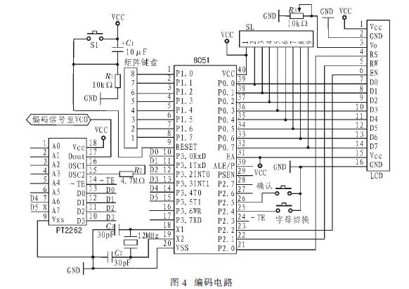
The control circuit is composed of a single chip microcomputer, a liquid crystal display, and a codec device. The coding circuit is controlled by the single-chip microcomputer to control the PT2262 to complete the writing of English short messages. Each English historical letter corresponds to one code group, such as A corresponds to 000000. B corresponds to 00000l, C corresponds to 0000l0 and so on. The English message is displayed on the LCD display and then sends the modulated signal to the transmitter circuit.
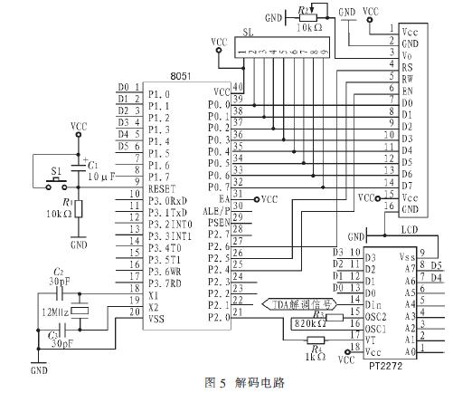
The decoder uses PT2272, and its address must be the same as the address of PT2262. PT2272 decodes the signal from TAD7010T and sends it to the single-chip microcomputer, where the single-chip microcomputer performs table look-up processing. That is, the received data is 000000, A is displayed, 00000l is B, 0000l0 is C, etc. English text message received. The encoding and decoding circuits are shown in Figure 4 and Figure 5, respectively.
3 software programming
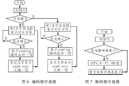
The control program is developed with Keil C51 high-level language. The program structure is simple, and the readability and portability are strong. Figure 6 is the coding program flow, and Figure 7 is the decoding program flow.
4 Test results
Testing the system, the range of the carrier frequency of the transmitting circuit is 32.832 ~ 40.128 MHz. By changing the value of N, a step of transmitting frequency of 64 kHz can be achieved; the Vpp of the modulated signal transmitted by the antenna = 600 mV; the received voice signal is clear, and the bit error rate of sending and receiving English short messages is extremely small.
5 Conclusion
The system realizes the transmission and reception of analog voice signals and digital English short messages. The PLL technology is used to ensure that the frequency stability of the transmission and the frequency stability of the crystal oscillator are on the same order of magnitude. The receiving part uses the highly sensitive frequency demodulator TDA7010T. PT2262 and PT2272, the peripheral circuit is simple and easy to adjust, the received sound signal is clear and bright after amplification, the error rate of English short messages is small, and the whole system works stably and reliably. In addition, the system can also be applied to the wireless transmission and reception of other analog signals and digital signals. It is only necessary to convert the modulated signal into a suitable voltage and load it at the modulation terminal A, and it can be transmitted. Pin 2 output.
Zinc Aluminum Alloy Wire, zinc is the matrix, through different aluminum content to meet the needs of different customers, and the use of advanced production technology, strict quality control, surface and inner quality is good and stable, with good mechanical properties. Using in film capacitor surface spray
Zinc Aluminum Alloy Wire,Blasting Materials,Anti-Corrosion Spraying Material,Ductile Iron Pipe
Shaoxing Tianlong Tin Materials Co.,Ltd. , https://www.tianlongspray.com