ADN8830 designed uncooled infrared focal plane temperature control circuit
This article focuses on a high-performance TEC temperature control circuit based on ADN8830 and its PID compensation network adjustment method.
Infrared technology has been widely used in military-civilian technology as an important means of discovering, detecting and identifying targets. The development of uncooled infrared focal plane array technology has greatly improved the performance of the system. Uncooled infrared thermal imagers use a focal plane array of thermal detectors that do not require refrigeration, and use infrared radiation to change the temperature of sensitive pixels on the focal plane, thereby changing the resistance to detect the temperature characteristics of the target. Therefore, only as much as possible to ensure that the reference temperature of each sensitive pixel in the focal plane array is stable and consistent, can the detection sensitivity of the thermal imager be improved, the difficulty of non-uniformity correction in the later stage of the system can be reduced, and ultimately the thermal image can be fundamentally improved The detection sensitivity of the instrument improves the imaging performance of the thermal imager. At present, semiconductor thermoelectric coolers (TEC) are used in actual uncooled infrared focal plane array detectors to stabilize the reference temperature.
1 Temperature control circuit design
TEC (Thermo Electric Cooler) is composed of two different semiconductor materials (P-type and N-type) to form a PN junction. When direct current passes through the PN junction, the electrons and holes in the two materials move across the PN junction The endothermic or exothermic effect (Peltier effect) will cause the PN junction to exhibit cooling or heating effects. Changing the current direction can realize TEC cooling or heating, and adjusting the current size can control the heating and cooling output .
The method of using TEC to stabilize the target temperature is shown in Figure 1. 
The first part in Figure 1 is the temperature sensor. This sensor is used to measure the temperature of the target object placed on the TEC side. The desired target object temperature is expressed by a set point voltage, compared with the voltage generated by the temperature sensor representing the actual target object temperature through a high-precision operational amplifier, and then an error voltage is generated. This voltage is amplified by a high-gain amplifier, and also compensates for the phase delay caused by the hot and cold ends of the target object, and then drives the H-bridge output, which also controls the direction and magnitude of the TEC current. When the temperature of the target object is lower than the set point temperature, the H bridge drives the current with a certain amplitude toward the TEC heating direction; when the temperature of the target object is higher than the set point temperature, the H bridge reduces the TEC current Reverse the current direction of the TEC to reduce the temperature of the target object. When the control loop reaches equilibrium, the current direction and amplitude of the TEC are adjusted, and the temperature of the target object is also equal to the set temperature.
In this design, the TEC controller ADN8830 from Analog Devices is used for TEC control. ADN8830 is one of the best single chip high integration, high output efficiency, high performance TEC power drive modules currently used to set and stabilize the temperature of TEC. In typical applications, the maximum temperature drift voltage is less than 250 mV, Can make the target temperature error less than ± 0.01 ℃. Each voltage applied to the input of the ADN8830 corresponds to a target temperature set point. Appropriate current through the TEC will drive the TEC to heat or cool the infrared focal plane. The temperature of the infrared focal plane is measured by a negative temperature coefficient thermistor and fed back to ADN8830, which is used to adjust the system loop and drive the TEC.
The ADN8830 designed here is used to realize the uncooled infrared focal plane temperature control circuit as shown in Figure 2. 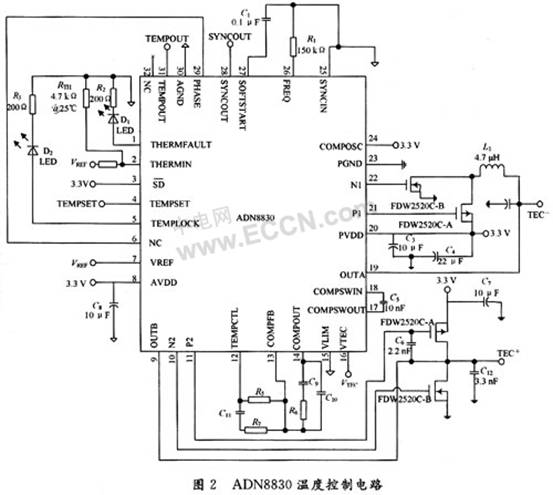
The resistor RTH in Figure 2 is the thermistor included in the uncooled infrared focal plane assembly. The choice of resistance R4 is related to the temperature characteristics of the thermistor RTH and the ambient temperature. The resistance of the thermistor RTH does not decrease linearly with increasing temperature. The resistance of the resistor R4 should be calculated according to equation (1): ![]()
In the formula: RT1 and RT3 respectively represent the resistance value of the thermistor at the two upper and lower limits of the operating temperature, RT2 is the resistance value of the thermistor at the average temperature. In practical applications, the two limit of the working temperature can be 5 ℃, 45 ℃, the average temperature is 25 ℃. By referring to the thermistor temperature curve, RT1 = 10.735 kΩ, RT2 = 4.700 kΩ, RT3 = 2.250 kΩ, and the value of resistance R4 is calculated to be 3.304 kΩ, taking R4 = 3.300 kΩ.
The control principle of the ADN8830 temperature control circuit is to control the temperature by sampling the voltage on the thermistor and the temperature set by the normal operation of the uncooled infrared focal plane, thereby adjusting the direction and magnitude of the current flowing in the refrigerator. The set voltage value of pin 4 (TEMPSET) of ADN8830 should be calculated according to formula (2): ![]()
When the setting temperature = 25 ° C, the thermistor RTH = 4.7 kΩ, the reference voltage VREF is provided by the chip internally, is 2.47 V, then VSET is 1.45 V.
2 PID network adjustment and parameter setting
PID (ProporTIon Integrator DifferenTIator) integral differential proportional adjustment compensation network is the most critical part of TEC temperature control, and is a key factor that affects the response speed and temperature stability of TEC controller. PID control technology is used as the core to reduce static errors and improve control accuracy. PID is equivalent to an amplifier with adjustable magnification. Proportional operation and integral operation are used to improve the adjustment accuracy. Differential operation is used to accelerate the transition process, which solves the contradiction between the adjustment speed and accuracy. The mathematical model of PID can be expressed by formula (3): ![]()
In the formula: Kp is the proportional coefficient; T1 is the integral time constant; TD is the differential time constant.
The ADN8830 TEC controller uses an external compensation network, requiring only a few resistors and capacitors, as shown in Figure 3. Different application designers can adjust the compensation network according to their thermal load characteristics to achieve the best temperature setting time and stability tolerance, but the conversion cycle of the compensation network has a greater impact on the stability of the control system. In order to ensure the stability of the temperature control, the conversion period of the compensation network must be smaller than the thermal time constant of the TEC and the temperature sensor. However, the thermal time constants of TEC and temperature sensors are an indescribable factor, and network parameters cannot be designed by calculation. For the PID network of Figure 3, the parameters can usually be optimized through the following debugging steps: 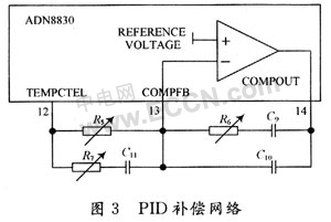
(1) Short circuit capacitor C9 and open circuit C11, leaving only resistors R6 and R5 to form a simple compensation ratio network;
(2) Increase the ratio of resistors R6 and R5, thereby increasing the gain until the voltage across the TEC begins to oscillate, and then reduce the ratio of R6 and R5 to 1/2 of the original;
(3) Connect the capacitor C9 in series to the compensation network, and reduce the value of the capacitor until the voltage across the TEC starts to oscillate, and then double the value of the capacitor C9. The initial value of the capacitor C9 is based on equation (4) to make the unit The gain is 0.1 Hz; ![]()
(4) Short-circuit resistance R7 and add capacitor C11 to make the voltage across the TEC start to oscillate. At this time, reduce the capacitor C11 or reconnect the resistor R7 to stabilize the voltage across the TEC
(5) Change the voltage value of TEMPSET to adjust the voltage stabilization time at both ends of TEC. The change of TEMPSET is about 100 mV, and then reduce the capacitance C11, C9 and resistor R7 to reduce the stabilization time, but will cause the output voltage to overcharge;
(6) Add a feedback capacitor C10 in parallel with R6 and C9. The feedback capacitor C10 can improve the stability of the system without increasing the stability time. Generally 330 pF ~ 1 nF capacitance is more appropriate.
The temperature control circuit designed in this paper uses the PID network structure of Figure 3. When C9 = 22μF, C10 = 330 pF, C11 = 1μF, R7 = 1.388 MΩ, R5 = 1.092 MΩ, and R6 = 175 kΩ, the system changes from ambient temperature to The establishment time of the target temperature is within 10 s, the accuracy can reach 0.01 ℃, and can maintain long-term stability. 
3 Performance test
The experimental test was conducted at room temperature. The signal shown in Figure 4 is the voltage change of pin 30 (TEMPOUT) of ADN8830. The voltage change is consistent with the temperature change detected by the sensor, so the characteristics of the voltage change can be derived from Get the characteristics of temperature changes. As shown in Figure 4, it can be seen that after 8.4 s, the voltage is stable at the preset voltage of 1.45 V, which means that the settling time of the temperature from the ambient temperature to the target temperature of 25 ℃ is 8.4 s, and the overcharge is small, and Reached stability. The circuit has the function of normal work indication and work failure alarm indication. When the temperature detected by the thermistor reaches the set temperature (the set temperature of this circuit is 25 ℃), pin 5 (TEMPLOCK) of ADN8830 outputs a high level, indicating that the operating temperature of the uncooled infrared focal plane has reached the set temperature At this time, the light-emitting diode D1 emits light; when pin 1 (THERMFAULT) outputs a high level, it indicates that the circuit works abnormally, and the light-emitting diode D2 is lit. 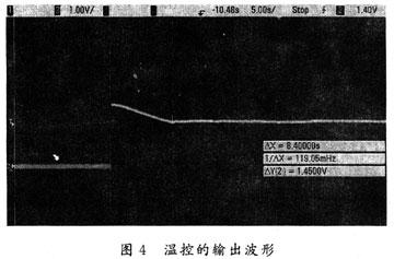
4 Conclusion
The uncooled infrared focal plane temperature control circuit based on ADN8830 designed in this paper has high efficiency, low power consumption and small volume. It has been proved by practical application that the temperature can be controlled at a preset temperature, and the accuracy can reach 0.01 ℃. The external compensation network formed by a few simple resistors and capacitors can control the temperature at a preset temperature within 10 s and keep the entire temperature control system in a stable working state for a long time.
Safety Light Curtain,Safety Curtain,Laser Safety Light Curtain,Safety Optic Light Curtain,Security Light Curtain,Press Brake Safety Light Curtains
Jining KeLi Photoelectronic Industrial Co.,Ltd , https://www.sdkelien.com