This paper gives several motor protection schemes. It not only has fast response and reliable control, but also greatly reduces the production cost of the protection device. Compared with the traditional protection circuit, the protection circuit saves the energy consumption of protection devices such as thermal relays and AC contactors, and is integrated with the motor. After testing and verification, the effect is good.
1 Principle of current detection
To achieve overcurrent protection, the primary task is to detect the motor current. There are usually 2 methods for detecting current:
(1) Small resistance non-inductive sampling resistor. Constantan wire or patch is usually used. This is an inexpensive solution, but pay attention to the selection of the resistance of the sampling resistor. The power should be large enough, and the inductance of the resistor should be small to exclude the inductance caused by the inductance at both ends of the resistor. Voltage drop.
(2) Hall current sensor. It is suitable for drive development, and adopts the current measurement of the LA28-NP Hall current sensor of LEM Company. Its advantages are high accuracy and high reliability.
There are also 2 methods to choose from at the current sampling location:
(1) Phase current sampling. Put the sampling resistor or Hall current sensor in each phase, assuming that the three-phase current is ia, ib and ic, and because the three-phase current of the brushless motor has the following relationship: ia + ib + ic = 0, so as long as the detection The current information of the other phase can be obtained from the two-phase current in the brushless motor.
(2) Sampling of bus current. Generally, the sampling resistor or power sensor is placed on the negative side of the busbar to conduct current sampling.
The following introduces a method of sampling bus current based on LEM Hall current sensor, which has high accuracy and high reliability.
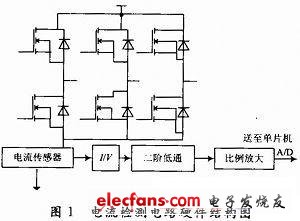
Place the Hall sensor LA28 between the negative side of the busbar and the ground for current detection. LA28 reduces the detected primary current by a ratio of 1 000: 1 to obtain the secondary current. The secondary current is converted after passing through the I / V circuit In order to facilitate the amount of voltage collected by the A / D (analog / digital conversion module), but the voltage signal output by the I / V contains rich harmonic components of PWM chopping, so if you send it directly to the A / D port of the microcontroller, it will No voltage information can be detected, so a signal conditioning circuit needs to be added, that is, the voltage obtained by the I / V circuit is sent to a Butterworth second-order low-pass filter for low-pass filtering. After low-pass filtering, the higher-order harmonic components can be filtered to obtain a DC component. At the same time, in order to facilitate the A / D port acquisition, the filtered small voltage signal is proportionally amplified and then sent to the A / D port for detection. The schematic diagram of this hardware circuit is shown in Figure 1.
The I / V circuit is shown in Figure 2.
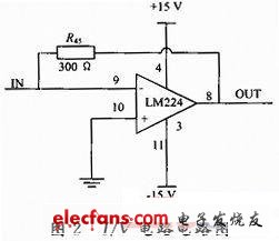
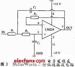
Figure 3 shows the design method of the second-order low-pass filter. In actual design, make R1 = R2, C1 = 2C2, can realize -40 dB / 10 frequency response. The calculation formula of its cut-off frequency is:
In the actual circuit, the resistance and capacitance values ​​are R = 100 kΩ, C = 1μF, and the cut-off frequency f = 1.126 Hz, so as to filter out the middle and higher harmonic components of the square wave voltage signal, and then obtain a stable DC component.
Fiber Optic Patch Cord is important of optical network.they have same or different connectors which are installed on the end of fiber optic cable. The Fiber Optic Patch Cord series comes with a comprehensive collection of lengths and connectors to fulfill your demand for the deployment.
SC To FC Fiber Optic Patch Cord
Fiber Patch Cord,Fiber Patch Cables,Bulk Fiber Optic Cable,FC SC Fiber Patch Cord
Chengdu Xinruixin Optical Communication Technology Co.,Ltd , https://www.xrxoptic.com