In high-end audio equipment, careful selection of resistors is one of the best ways to avoid or minimize noise and distortion in the signal path. This article describes the generation of noise in resistors made using various existing resistor technologies, and quantifies each type of typical noise insertion.
Noise in the resistor
The total noise of the resistor consists of multiple components. Closely related to various audio applications are thermal noise and current noise.
The distinguishing feature of thermal noise is independent of the resistance material. In fact, if the resistance and temperature are the same, the thermal noise level of any type of resistor is the same. Thermal noise voltage power spectral density (PSD) ST [V2 / Hz] is evenly distributed over the entire frequency range. It can be expressed by the following expression:
among them
R-resistance of the resistor [W], T-temperature of the resistor [K], k = 1.3807´10-23 J / K-Boltzmann constant.
On the other hand, current noise has a direct relationship with the type of resistive material. It is found through experiments that the voltage spectral density SE of the current noise is proportional to the square of the DC voltage drop U on the resistor and inversely proportional to the frequency f:
C is a constant that depends on the resistance element material and its manufacturing process.
Figure 1 shows the spectral density S of the total noise voltage in the resistor.
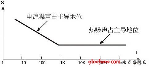
Figure 1. Spectral density of the total noise voltage in the resistor
The current noise level in a resistor is usually expressed in units of μV / V or decibel (according to the noise index [NI] dB)
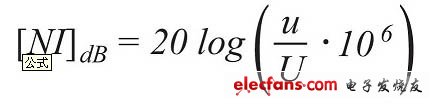
Where u is the rms noise voltage over the decimal bandwidth, and U is the DC voltage drop across the resistor. The unit of measurement for both u and U is volts.
The lower the noise figure, the lower the current noise level in the resistor.
The chart below shows the noise figure of resistors manufactured using different technologies.
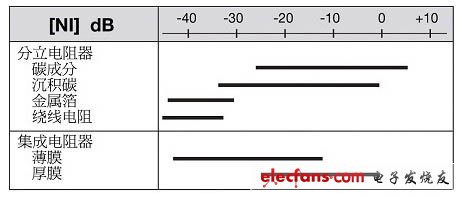
Figure 2. Average noise figure of commercial resistors
As shown in the graph, resistors based on composite resistive materials (such as carbon and thick films) have the highest current noise level. Why? This is due to the significant heterogeneity of these resistance element materials. The conductive paths in these composite materials are formed by conductive particles in contact with each other in the isolation matrix. When current flows through unstable contact points in these "contact locations", they generate noise.
The thin-film resistor has a relatively strong homogeneous structure, so the noise is low. The thin film is formed by depositing or evaporating resistive materials such as tantalum nitride (TaN), silicon chromium (SiCr) and nickel chromium (NiCr) on the ceramic substrate. Depending on the resistance value, the thickness of this layer generally ranges from 10 to 500 Angstroms. Noise in the film is caused by inclusions, surface defects, and uneven deposition (more pronounced when the film is thinner). This is why the thicker the resistive film, the lower the resistance value and thus the lower the noise level.
Among the resistors with large metal resistance elements, the lowest noise levels can be observed: foil resistance and wire-wound resistance. Although the wire is made of a metal alloy similar to the foil material, additional noise may be generated at the junction of the thin wire of the resistance element and the thicker resistor terminal. In foil resistors, the terminal and the resistive element are parts of the same foil, so this problem is avoided. However, the main drawback of wire wound resistors is their inductance. Inductance can cause chopping of signal peaks and heavy dependence on the impedance of the resistor at the signal frequency. In addition, special attention must be paid to the following effects related to the reactance of the wound resistor:
Audio amplifiers may self-oscillate above 5 MHz to 50 MHz, affecting audio quality.
The equivalent series inductance (ESL) will cause a large phase shift and affect the audio tone.
The coil may play a role in picking up electromagnetic interference (EMI), which exceeds the usual current noise level.
Foil resistors avoid these problems because they are formed by chemically etching large flat metal foils. Therefore, the current flows in adjacent current-carrying paths in opposite directions, eliminating parasitic inductance in these paths. Moreover, the path-to-path capacitance is in series, which has the effect of minimizing the parasitic capacitance of the resistor. These low inductance / capacitance resistors are characterized by unmeasured peak-to-peak signal distortion.
Foil resistors in high-end audio applications
High-end analog audio applications require low inherent noise, high linearity of amplification, and minimal dynamic distortion. A typical audio amplifier consists of a voltage pre-amplifier (pre-amplification) and a power amplifier (final drive). The voltage preamplifier handles low-level signals. This is why the inherent noise level is so important. The resistor is one of the main noise sources in the amplifier.
The main requirements for audio power amplifiers are high linearity of amplification and minimal dynamic distortion. The characteristic of the foil resistor is that the inherent non-linearity of the resistive element (made of large metal) is very low. Wire-wound resistors and some metal film resistors have similar non-linear characteristics, but in the real world, the inherent linearity of the resistor is not sufficient to ensure amplification linearity.
Audio System,Digital Stereo Amplifier,Professional Audio System,Dolby Digital Plus Home Theater
The ASI Audio Technology Co., Ltd , https://www.asi-sound.com