1 Introduction
Virtual instrument is a new type of instrument module produced by the combination of machine technology and instrument. It is usually composed of computer, modular functional hardware and visual software with data processing and process control. This system uses LabView6.1 graphic language programming produced by NI company to realize. LabView uses icons instead of traditional text codes for programming. The program modules represented by icons are all mature program modules developed by NI. Therefore, the use of LabView programming can greatly improve the efficiency of system development.
Fetal monitoring and perinatal monitoring are important monitoring measures in obstetrics. Commonly used fetal monitoring methods are: ultrasound Doppler monitoring, fetal heart sound monitoring and fetal electrocardiographic monitoring. Among them, fetal electrocardiographic monitoring, because it extracts fetal electrocardiographic signals from the maternal abdomen, is non-invasive to the mother and the fetus, especially to observe the fetal electrocardiogram at the same time, which has obvious advantages and is a commonly used diagnostic method in obstetrics.
Although the abdominal ECG signal is easy to pick up, the maternal abdominal signal is complex and the signal-to-noise ratio is low. In particular, the general maternal ECG signal is 10-20 times larger than the fetal ECG signal, and the fetal ECG is about 10% -30%. The maternal ECGs coincide, forming a complex QRS complex, and the spectrum of the fetal ECG overlaps with the maternal ECG spectrum. These factors have brought great difficulties to the detection of fetal ECG. Scholars have explored a series of signal processing methods to solve this, including: matched filtering method, adaptive filtering method and so on. This system uses the commonly used matching filter method.
2 Implementation of the system
2.1 System Overview
The system consists of two parts: hardware data collector and ordinary PC, connected by RS-232 port. The application program on the PC is implemented with the graphical programming language LabView6.1. The data sampled by the hardware data collector is sent to the PC in serial communication. The software on the PC reads the waveform data through the RS-232 interface module and sends it to the pre-processing module. Perform matching filtering to remove the interference of the mother's ECG, and finally display the waveform of the fetal ECG signal on the display. In addition, the PC can also control the working state of the hardware data collector through serial communication, such as adjusting the gain and time constant.
2.2 Hardware signal acquisition system
The system hardware is composed of pre-amplification, power frequency notch, main amplifier, single-chip system and so on. The pre-amplifier appropriately amplifies the signal transmitted from the lead and sends it to the notch of the power frequency trap to prevent possible excessive power frequency interference from blocking the system amplification channel. Subsequently, after the signal is amplified by tens of thousands of times through the main amplifier and the final amplifier, the A / D controlled by the single-chip microcomputer performs 400 & TImes; 12 bits / s sampling, and the data is sent to the PC for processing via the RS-232 interface. The hardware part is a high-precision ECG signal acquisition system controlled by PIC microcontroller. The system uses 12-bit high-precision serial output A / D converter AD7895. The sampled data will be sent to the PC through the serial port according to the following frame format after being processed by the single-chip microcomputer. The system sampling rate is 400Hz and the data transmission rate is 19.2kbps. This system takes low power consumption as the main design idea, its working current is less than 3mA, and it can be powered by serial port without external power supply.
Among them, 12 Xs represent the data obtained by 12-bit A / D sampling; 00 and 11 are the flag bits, 00 represents the high 6 bits and 11 represents the low 6 bits. In addition, the hardware part also receives the control word of the PC.
2.3 Software
The software part is divided into 3 parts: RS-232 interface module, signal pre-processing, and matched filtering algorithm. Among them, matched filtering includes correlation detection and waveform cancellation.
2.3.1 RS-232 interface module
(1) Serial port power supply. Because the working current of the hardware data collector is relatively small, the system uses the idle handshake signal line in RS-232 to make the power supply to make it work. Therefore, before the main program opens the serial port to read the data, the hardware data collector must be powered up. Keep it in working condition. Use Serial Line Ctrl.Vi module in LabView, put RTS and DTR into corresponding electronics; (2) Serial port read and write. Because the hardware data collector continuously sends out data at a rate of 19.2kbps during the entire working period, for the convenience of data processing, the Serial Read With TIme-out FT.vi module is used to ensure that it is read from the serial buffer every time Measure even number of data. Use the Serial Port Write.vi module to send the control word to the hardware module. The control word is sent using the new event-driven function in LabView6.1.
2.3.2 Signal preprocessing
The main function is to filter out power frequency interference and suppress baseline drift.
Because the hardware system uses serial port power supply, 50 Hz power frequency interference is often mixed in the collected signals, which must be suppressed. The suppression of power frequency interference can be achieved from two aspects of hardware and software. In terms of hardware, power frequency interference is a common-mode signal, and high-quality preamplifiers, good shielding, and excellent power modules can be designed to reduce power frequency interference to the system. In terms of software, a 50 Hz digital notch method is used. The digital trap of this system is realized by Equi-Ripple Band-Stop PtByPt.vi control in Lab-View6.1 Signal Processing Toolbox.
There are many reasons for the baseline drift. Among them, the slight sliding between the surface electrode and the skin due to movement and the parameter change caused by the thermal effect of hardware components are the main reasons. This system uses nonlinear high-pass filtering to suppress baseline drift. The specific method is to obtain the baseline signal by median filtering the abdominal electrical signal and subtract it from the original abdominal signal. This system uses the Median Filter PtByPt.vi control. The actual processing effect is shown, A is the original abdominal signal; B is the baseline signal after median filtering; C is the abdominal signal after suppressing the baseline drift.
2.4 Matching filtering algorithm
2.4.1 Generation of data queue
Queue is a commonly used data structure, this system uses this data structure for matching filtering. However, the existing queue control queue of LabView6.1 does not meet the usage requirements, and a new one must be created. Here a similar approach is used in the C language to create an N-element array variable main Buffer and move the data from the tail to the head continuously. It is a double-precision floating-point number queue with a long pair of 1000 implemented by LabView programming. The difference from the C language implementation is that the number of data movements in the queue is 1000, not 999. This is because LabView initialization is different from C language. In LabView, if a cell of the array is not attached, then the cell is not initialized.
Therefore, if N = 999, the 998th cell will be initialized, and the 999th cell will not be initialized because it is a read, which will invalidate subsequent new data input operations.
2.4.2 Related detection algorithms
The cross-correlation operation of the signal and the detection template, where: S table does not go through the abdominal electrical signal that suppresses the baseline operation and removes the power frequency interference; T represents the detection template inside the system. After the cross-correlation operation, R peak detection can be performed. The cross-correlation operation uses the ColssCorrelaTIon.vi control in Signal Processing Toolbox.
R peak detection is actually to perform peak detection on the result of the cross-correlation operation to obtain the precise position of the mother's ECG R peak. Use the peak detection control Threshold Peak Deicer PtByPt.vi that comes with LabView system to detect.
2.4.3 Waveform cancellation algorithm
The basic idea of ​​the waveform cancellation algorithm is to weight the average of the current mother's ECG QRS complex and the previously obtained QRS complex template to create a new QRS complex, and subtract it from the current QRS complex to filter out the mother's heart Electricity. The clinical experiment is independent of the timer interrupt service subroutine outside the main program to complete the display function. The program design is simple and clear, and it is readable. The 24C01C used in the system is easy to operate, except 3 pins, the other pins can be grounded.
3 System software
The system software consists of a main program, a display digital interrupt service subprogram, a power control interrupt service subprogram, a timer interrupt service subprogram, and a fault handling subprogram. The visual dwell time of human eyes is 20ms, and each display time interval must be less than 20ms. Display interruption Interruption interval 9ms each time, alternately display 3 LEDs, each digit display interval is 18ms (<20ms), can achieve a stable visual effect. The timer interrupt service subroutine includes up-counting and count-down, where the count-down is divided into timing in units of min and timing in units of s. The functions completed by the fault handling subroutine are to shut down the system and interrupt, turn off the heating output, determine and display the type of fault (short circuit, open circuit, and temperature exceeding the standard) based on the sampled temperature, issue an alarm, and wait for the user to confirm the fault information. For the convenience of programming, the system has specifically compiled sub-programs for key detection and confirmation, sub-programs for converting from D, sub-programs for voltage / temperature conversion, reading EEPROM, and writing EEPROM.
4 Conclusion
The automatic decoction machine has been welcomed by major manufacturers and pharmaceutical manufacturers for its outstanding advantages. Of course, it also has some problems that need to be solved, that is, how to solve the first decoction and then the next problem, and increase the concentration function. These problems need to be continuously improved in further practice. During the process, it was found that the traditional template update is not strong in tracking the changes of the QRS complex of the mother's ECG. In some cases, the QRS complex of the mother's ECG cannot be completely filtered out. This system improves this method. When the system is initialized, a template library with a capacity of N is created, and the detected mother's ECG QRS complex is stored in the library to replace the originally enrolled mother's ECG QRS complex. , And then weighted average according to the priority principle of new high and old low. Weight coefficients of QRS complexes of each mother's ECG.
The algorithm is expressed in the form of a signal flow graph. Demonstrate the effect of the system on the abdominal electrical signal after matching filtering processing, A is the electrical signal extracted from the abdomen; B is the fetal ECG signal after the improved template update method; C is the fetal ECG signal using the traditional template update method, * Indicates the remnants of the mother's ECG.
5 Conclusion
The system hardware does not need additional power supply, the system structure is simpler. The software uses LabView6.1 for graphical programming, and directly uses a variety of mature software modules provided by NI Company, thus greatly saving system development time and cost. This system has the function of signal baseline correction, and improves the traditional matching filter template update method. After nearly 20 clinical tests, all have achieved good results. This system still has room for improvement in the identification of fetal ECG groups.
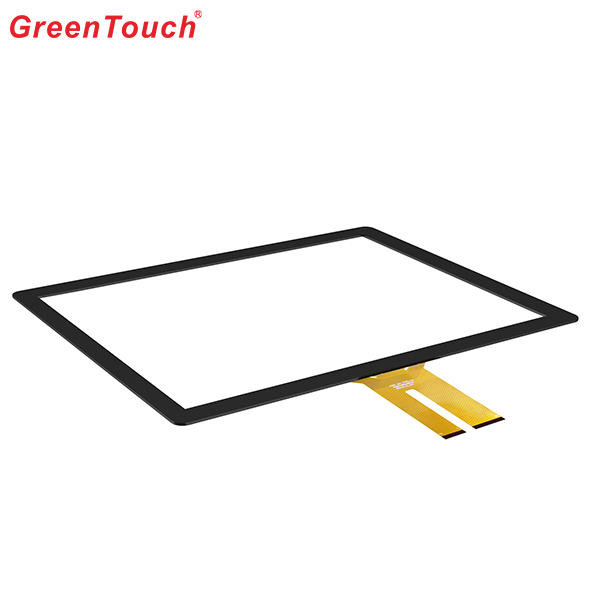
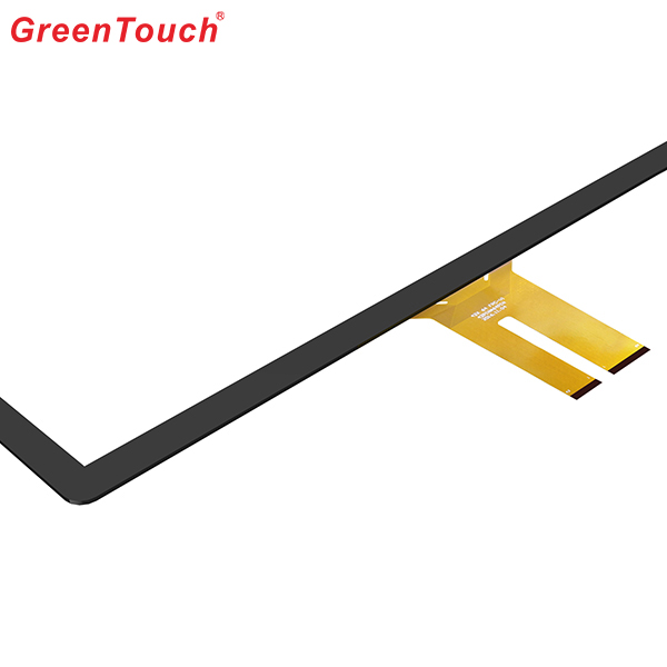
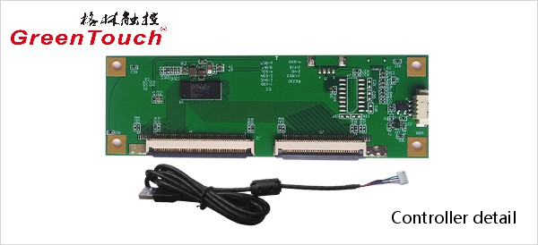
This product response time is shorter than resistive tonch screen's with a good touch.It is widely used to Phone,Tablet,E-book,gaming device by hands holding,Touch Monitor,GPS,All-In-One and so on.GreenTouch projected capacitive touch technology is with fast and sensitive response, the design with frame (without frame is optional) makes it looks professional and generous. The model is designed for high-intensity and high-frequency business environments.
Product show:


Capacitive Touch Screen Panel,Android Touch Screen,Portable Touch Screen,Pcap Touch Screen,POS Terminal Touch Screen,Mini Capacitive Touch Screen
ShenZhen GreenTouch Technology Co.,Ltd , https://www.bbstouch.com