Abstract: This paper introduces the working principle of phase-locked frequency discrimination circuit and the structure and characteristics of analog phase-locked loop chip NE564, and uses this chip to design a 41.4MHz FM demodulation circuit, which has strong practicability.
0 Introduction Frequency modulation (FM) demodulation is called frequency detection, or frequency discrimination for short. There are many ways to realize FM wave demodulation. Common methods are: a. Slope frequency discrimination, phase frequency discrimination, and proportional frequency discrimination. These frequency discriminator circuits require a large number of components such as resistors and capacitors. The circuit form is relatively complicated and not easy to integrate; b. Shift-phase product frequency discrimination and pulse mean frequency discrimination. These frequency discriminators are easy to integrate, but the internal noise of the phase-shift product frequency discriminator is relatively large. The pulse average frequency discriminator has good linearity and frequency bandwidth, but the center frequency range is low; c. Phase-locked loop frequency discrimination, which uses modern phase-locked technology to achieve frequency discrimination, has the advantages of stable operation, low distortion, high signal-to-noise ratio, etc., so it is widely used in communication circuit systems.
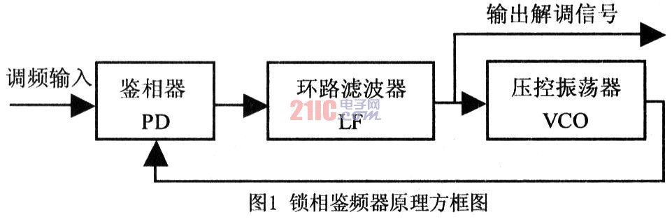
1 Working principle of phase-locked frequency discriminator The principle block diagram of phase-locked frequency discriminator is shown in Figure 1. When the input is a frequency-modulated wave, if the bandwidth of the loop filter is wide enough so that the output voltage of the phase detector can pass smoothly, the VCO (voltage controlled oscillator) can track the instantaneous frequency in the input frequency-modulated wave that reflects the change in modulation law , That is, the output of the VCO is an FM wave with the same modulation law. At this time, the control voltage output by the loop filter is the required demodulation voltage of the FM wave. Analog PLL NE564 chip can be used to design FM demodulation circuit.
2 The structure and characteristics of the analog phase-locked loop NE564 The maximum operating frequency of the analog phase-locked loop SE564 chip can reach 50MHz. It uses a + 5V single power supply. The circuit design uses few components. The key steps are to set the center frequency and how to filter the two. Aspects. It is especially suitable for the modulation and demodulation of FM signal and FSK (frequency shift keying) signal in high-speed digital communication, and does not need to connect a complex filter. The chip uses a bipolar process, the circuit is composed of six parts: limiter, phase detector, voltage controlled oscillator, amplifier, DC recovery circuit and Schmitt trigger. The internal structure is shown in Figure 2.
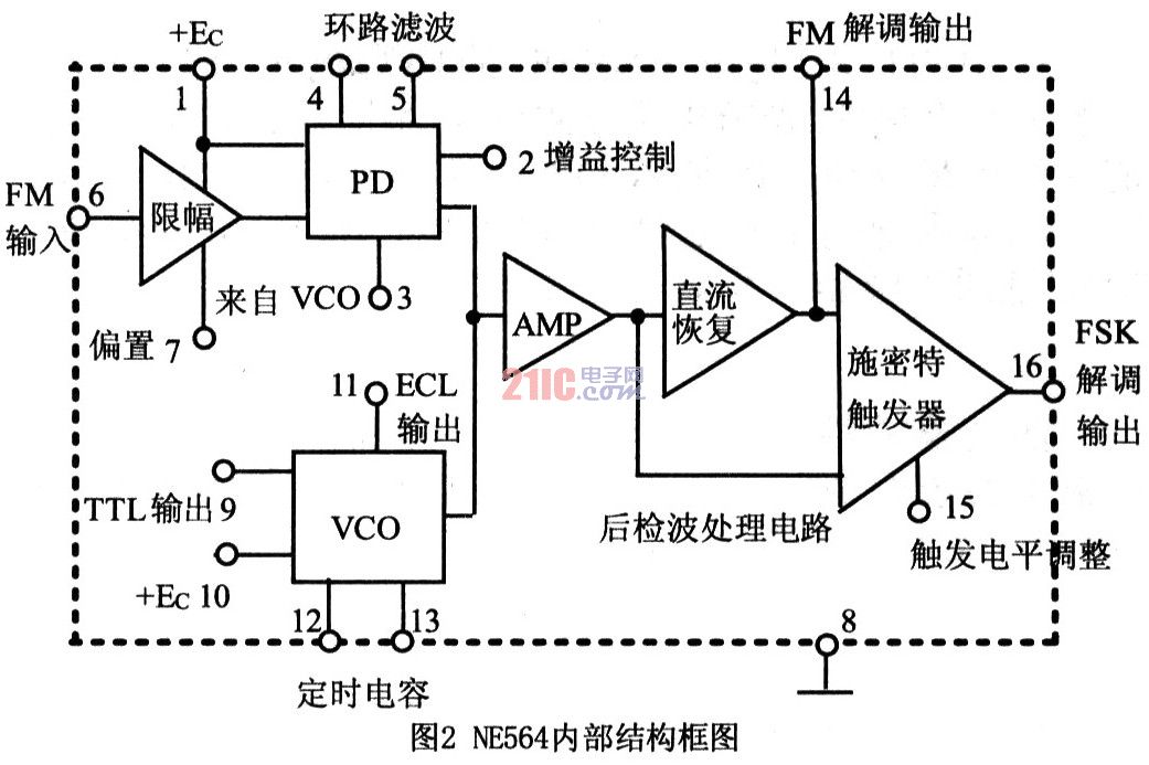
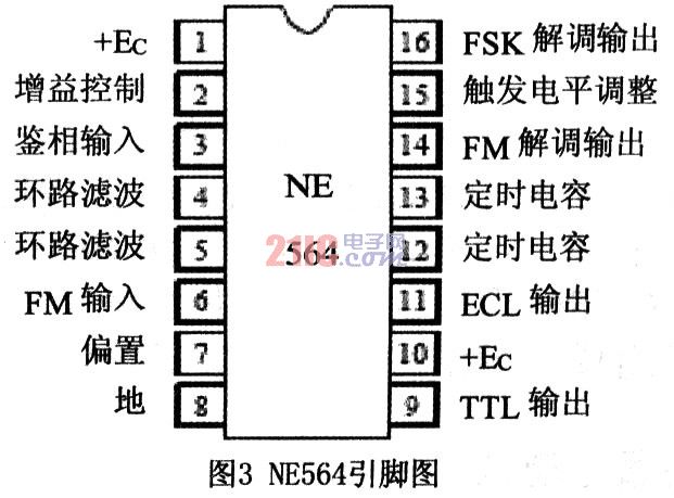
In Figure 2, the limiter consists of a differential circuit, which can suppress the parasitic amplitude modulation of the FM signal; the phase discriminator (PD) contains a limiter amplifier to improve the anti-interference ability of the AM signal: 4 and 5 feet are composed of external capacitors Loop filter, used to filter the ripple in the DC error voltage output by the comparator; Pin 2 is used to change the gain of the loop; Pin 3 is the feedback input of the VCO; VCO is an improved emitter-coupled multivibrator The oscillator has two voltage output terminals, 9 feet output TTL level, 11 feet output ECL level. A fixed resistor is connected inside the VCO, and only a timing capacitor can be connected to generate oscillation; the Schmitt trigger's hysteresis voltage can be adjusted by connecting a 15-pin external DC voltage to eliminate the phase jitter of the 16-pin output signal. The SE564 package diagram is shown in Figure 3.
3 FM demodulation circuit design Use NE564 to form a 41.4MHz FM circuit, as shown in Figure 4. The voltage Vi of the FM input signal is ≥100mV, and the frequency of the modulation signal fΩ = 1KHz. The component parameters of the circuit are designed as follows:

Dl, D2 in the picture are limiting diodes. C1 is the input coupling capacitor, and R1 and C2 form the input bias filter of the limiting amplifier to filter out clutter in the FM signal. R3 and RP provide input current I2 to pin 2 to control loop gain and VCO lock range. The relationship between total resistance R and current 12 is: 
The 1.3V in the formula is because the 13 pin voltage of NE564 is 1.3V, I2 is generally a few hundred milliamperes, adjust the potentiometer RP to make the loop gain and VCO lock range reach the best value. R4 is a pull-up resistor that must be connected to the VCO output. C3, C4 and the two internal corresponding resistors (resistance R = 1. 3kΩ) form a first-order RC low-pass filter. Its cut-off frequency is: 
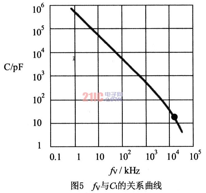
The performance of the filter has a certain effect on the speed of the loop lock time, and the values ​​of C3 and C4 can be changed according to requirements. The relationship between the VCO's natural oscillation frequency fv and the timing capacitor Ct is: 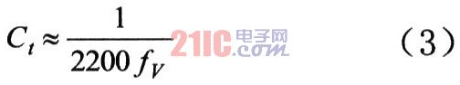
When the working frequency is 41.4MHz, from the equation (3) or the relationship between the oscillation frequency fv and Ct. 5, it is concluded that Ct≈11pF, which can be used in parallel with 6pF and 3 / 20pF capacitors. C5 and C6 are used to filter out high and low frequency AC components in the power supply. C7, C8 and R5 form a π-type filter, used to filter out harmonic components in the output signal.
This circuit is debugged, the center frequency works at 41.4MHz, the frequency deviation can reach more than 1MHz, and the output voltage is O. Above 4V.
For more knowledge of PLL, please visit http: //PLL.html
Wall Mount Industrial Touch Pc, compatible with mini motherboards help to configure the device with multiple expansions, and provide the flexibility and versatility for diverse configuration.
It can display production and process information, working as a easy- to- read Operator Guide Window , helping to improve productivity and efficiency in the work place.
Wall Mount Industrial Touch PC
Wall Mounted Pc,Panel Mount Touch Screen Pc,Industrial Computer,Wall Mount Industrial Touch Pc
Guangzhou TouchWo Electronics Co.,Ltd. , https://www.touchaio.com