LED, also known as LED, has the advantages of high efficiency, low power consumption, long life, high safety and environmental protection. As a new generation of light source, LED has gradually been accepted and has a preliminary application in the field of lighting.
1 traditional street lighting
At present, the types of light sources used for street lighting are mainly metal halide lamps, incandescent lamps and high pressure sodium lamps. Among them, high pressure sodium lamps are widely used due to their high luminous efficiency, long life, and strong penetrability. Its basic optical structure consists of a light source, a reflector and a transparent lampshade. Since the light radiation of the light source occupies almost the entire space, it is necessary to adopt the light distribution design of the optical system of the street lamp to achieve the luminosity parameter of the national standard street lamp. Generally, the reflector of a high-pressure mercury lamp type street lamp uses a parabolic groove for light distribution. It can be adjusted to illuminate the light in the desired area. The use of LED as a light source for new street lighting needs to find a new light distribution model for LED light source to achieve the luminosity index of street lighting.
2 LED street light optical design ideas
2.1 LED street light optical system
There are two broad types of optical structures for LED streetlights: projection and reflection. The projection streetlight optical structure usually consists of a rotating parabolic reflector and a lens, but a single such structure does not meet the lighting requirements of street lighting, so a lens must be used for re-lighting, as shown in Figure 1a. This method requires a high degree of cooperation between the reflector and the lens, which makes it difficult to design, install and maintain. The reflective optical structure, whose structure is shown in Figure 1b, is used by more and more optical designers because it only needs to be used for the light distribution design of the reflector. This paper also uses a reflective optical structure and a hybrid structure design of the reflector.
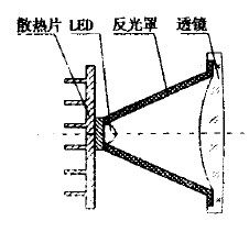
Figure 1a Projection structure
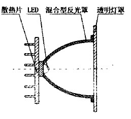
Figure 1b Reflective structure
2.2 Illumination optics computer aided design
Illumination optics design belongs to non-imaging optical design. It mainly studies optical systems from the perspective of energy transfer law. Basically, non-sequential ray tracing is used. The commonly used method for calculating illuminance is Monte Carlo method. This article uses Tracepm optical simulation software for simulation. The basic steps of the design are as follows:
(1) determining the number of LED light sources, establishing a model of the light source and setting its parameters;
   (2) establishing a three-dimensional model of the hybrid reflector structure;
   (3) Determine the arrangement of the LED light sources and simulate using optical software;
   (4) Analyze the simulation results and compare the difference between the simulation results and the road lighting distribution requirements;
   (5) According to the difference in the simulation results or the part that does not meet the requirements, the corresponding parameters are repeatedly corrected until the design requirements are met.
2.3 Hybrid structural design
   At present, reflective optical structures have been applied in more and more fields, and the difficulty lies in the design of the reflector structure, that is, how to design a reflective surface type that meets the needs of optical illumination and light distribution in Shenzhen. In order to direct the reflected light to a specified illumination area, there are two possible ways, that is, the light emitted by the light source is reflected toward the same side and reflected to the opposite side, as shown in Figures 2a and 2b, respectively.
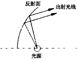
Figure 2a Same side reflection
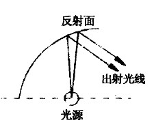
Figure 2b opposite side reflection
In view of the requirements of the illuminating characteristics and illumination range of the LED light source used, the reflective surface patterns in the X direction and the Y direction are designed to reflect the on-site road lighting. The light source is placed at the front focus F1 of the ellipsoid, as shown in Fig. 3 is an ellipsoidal reflection surface model. 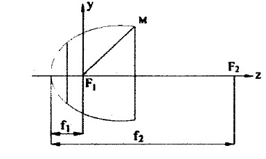
Figure 3 ellipsoid reflection surface model
The expression equation of the ellipsoidal reflection surface is:
Where a and b are the semi-major axis and the semi-minor axis of the ellipsoid, respectively.
And f1, f2 in Fig. 3 respectively represent the ellipsoid vertices to 2 focal points, the distances of F1 and F2, and the expressions are as follows:

By adjusting the dimensions of the long and short axes a and b of the ellipsoid, the length of the semi-focal length of the ellipsoidal reflecting surface can be changed, so that the angle of the outgoing light can be changed to ensure that the outgoing light can be illuminated in the desired illumination area.
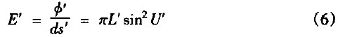
2.4 Calculation method of illuminance
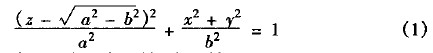
   The illuminance calculation formula currently used is usually based on the calculation model as shown in Fig. 4, where ds represents a small area ds' on the object surface near the point on the axis, representing a small area on the image surface near the point on the axis, U represents The square aperture angle, U' represents the image aperture angle, and the object plane brightness is L image plane brightness is L', and the luminous flux Φ emitted by the object side ds in the solid angle U range can be expressed as:

Then, the luminous flux φ' incident on the ds' from the exit pupil to the image surface micro-area is:

Thus, the illuminance E' of the image plane can be obtained as:
When the object space and the medium of the image space are converged, the image plane brightness L' is equal to the product of the object plane brightness L and the system transmittance Ï„0 , namely:

Then (6) can be expressed as:

Figure 4 Schematic diagram of illuminance calculation model
   2.5 LED light source arrangement
   At present, the luminous efficiency of a single LED is limited. To be applied to LED street lighting, multiple LEDs need to be arrayed in a certain shape. For the consideration of the cost of the lamp, it is desirable to use as few LEDs as possible while meeting the lighting requirements. This requires finding a suitable arrangement. According to the illumination characteristics of LED light source and the basic requirements of road illumination, this paper adopts a 10×6 array form, and simultaneously deflects each column of light source at different angles.
2.6 Simulation Results
Figure 5 shows the results of multiple simulations using optical software Tracepro.
Fig. 5a is a simulation effect diagram of the illumination area distribution. It can be seen from the figure that by controlling the design of the reflection cover and the arrangement angle of the light source, uniform illumination is basically formed in a given illumination area, thereby improving the utilization rate and reducing the light source. The light pollution protects the health of the human eye, and at the same time effectively improves the driver's identification of the road surface. And Figure 5b is the illuminance distribution map.
The wider curve in the figure represents the illuminance distribution in the 0 degree direction (ie, the vehicle traveling direction), and the narrower curve represents the illuminance distribution in the 9o degree direction. It can be clearly seen from Fig. 5b that the E illuminance distribution in the 9o degree direction is relatively uniform around 121x, and in the 0 degree direction, the illuminance varies from IOX to 141x: only the illuminance in the small area of ​​the edge region is lower than the average illuminance. However, it still basically meets the illumination requirements of 10X to 151x in the lighting area required by national standards.
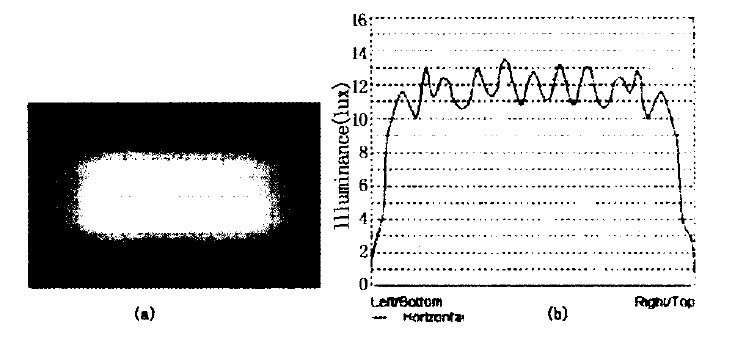
Figure 5 Simulation results
3 Conclusion
In this paper, the design of the hybrid reflector structure is carried out for the optical system of the LED street lamp. From the simulation results, the requirements for uniform rectangular light distribution in the illumination area are basically achieved. The next step will be how to improve the rectangular light distribution. The uniformity of illumination between the boundary and the illumination area, combined with the illuminating characteristics of the high-power LED light source itself, optimizes the deflection angle of the reflector and the light source to achieve the desired light distribution design, or from the perspective of a new type of reflector structure Research and exploration.
As a new type of light source, LED has the advantages of green, environmental protection and energy saving. It has been gradually accepted by people. With the development of semiconductor materials and the continuous improvement of production technology, LED street lamps will replace the traditional ones in the next five to ten years. Street lights of light sources, LED street lights will set off another revolution in the field of lighting.
| About Glass Fiber Series Wire |
The insulation material uses 160 pieces /250 pieces non-alkali yarn glass fiber yarn, which is characterized by thin insulation layer, light weight and protective effect on inner insulation.Impregnating varnish used modified epoxy paint, epoxy, conforms to the ROHS certification, with excellent electrical properties and high mechanical and damp and hot resistance, suitable for ac, dc motor, synchronous generator, dry type transformer and high temperature electric appliance coil and winding, the high voltage ac motor, large dc motor, large wind turbines, glass envelope envelope particularly suited to 10 kv transformer and large and medium-sized high-voltage motor winding.
Glass Fiber Copper Wire
Name
Insulation Glass Fiber Winding Wire
Conductor
Copper
Dimension(mm)
Round: 1.0 ~ 7.0
Rectangular: Thickness(a): 1.0 ~ 10.0
Width(b): 3.0 ~ 35
Insulation Material Type
Fiber Glass
Insulation Thickness
Singer, double or according to your requirement
Standard
IEC; ISO9000; ISO9001; IATF16949
Packing
100kg ~120kg ply-wood spool (250*500)
Application
Oil-immersed transformer windings, medium
and large electrical motor and power substations, etc.
Glass Fiber Aluminium Wire
Name
Insulation Glass Fiber Winding Wire
Conductor
Aluminum
Dimension(mm)
Rectangular: Thickness(a): 1.0 ~10.0
Width(b): 3.0 ~ 35
Insulation Material Type
Fiber Glass
Insulation Thickness
Single, double or according to your requirement
Standard
IEC; ISO9000; ISO9001; IATF16949
Packing
50kg~150kg ply-wood spool (250*500/
250*550/ 250*600)
Application
Oil-immersed transformer windings, medium
and large electrical motor and power substations, etc.
Glass Fiber Series Wire
Copper Flat Wire,Glass Fiber Series Wire,Double Glass-Fiber Copper Flat Wire,Fiberglass Copper Wire For Motor
HENAN HUAYANG COPPER GROUP CO.,LTD , https://www.huaonwire.com