Definition formula of receiving sensitivity
Abstract: This application note discusses the definition of spread spectrum system sensitivity and the method of calculating the sensitivity of digital communication receivers. This article provides the step-by-step derivation process of the receiver sensitivity equations, and also includes examples of specific numbers to verify their mathematical definitions.
In a spread spectrum digital communication receiver, the relationship between the link's measurement parameter Eb / No (the ratio of energy per bit to noise power spectral density) and the power value of the RF signal required to achieve a certain expected receiver sensitivity is from the standard noise figure Derived from the definition of F. Radio frequency engineers of CDMA, WCDMA cellular system receivers and other spread spectrum systems can use the derived receiver sensitivity equations to design. For any given input signal level, the designer can determine by weighing the spread spectrum link budget Receiver parameters.

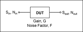
figure 1.
The following are the definitions of the parameters used in Figure 1, and they will also be used in the sensitivity equation:
Sin = available input signal power (W)
Nin = available input thermal noise power (W) = KTBRF where:
K = Boltzmann constant = 1.381 × 10⁻²³ W / Hz / K,
T = 290K, room temperature BRF = RF carrier bandwidth (Hz) = chip rate of spread spectrum system
Sout = available output signal power (W)
Nout = available output noise power (W)
G = equipment gain (value)
F = equipment noise figure (numeric value)
The definition is as follows: F = (Sin / Nin) / (Sout / Nout) = (Sin / Nin) × (Nout / Sout) Nin is represented by the input noise Nin: Nout = (F × Nin × Sout) / Sin where Sout = G × Sin gives: Nout = F × Nin × G The average power of the modulated signal is defined as S = Eb / T, where Eb is the energy in the bit duration, the unit is Ws, and T is the bit duration in seconds.
The relationship between the average power of the modulated signal and the user data rate is calculated according to the following formula: 1 / T = user data bit rate, Rbit unit Hz, resulting in Sin = Eb × Rbit According to the above equation, the device output is expressed in Eb / No The signal-to-noise ratio is: Sout / Nout = (Sin × G) / (Nin × G × F) =
Sin / (Nin × F) =
(Eb × Rbit) / (KTBRF × F) =
(Eb / KTF) × (Rbit / BRF), where KTF represents the noise power (No) within a 1-bit duration.
Therefore, Sout / Nout = Eb / No × Rbit / BRF In the radio frequency band, BRF is equal to the chip rate W of the spread spectrum system, and the processing gain (PG = W / Rbit) can be defined as: PG = BRF / Rbit So, Rbit / BRF = 1 / PG, thus the output signal-to-noise ratio is obtained: Sout / Nout = Eb / No × 1 / PG. Note: For systems without spread spectrum (W = Rbit), Eb / No is numerically equal to SNR. Receiver sensitivity equation For a given input signal level, in order to determine SNR, use the noise figure equation to express Sin: F = (Sin / Nin) / (Sout / Nout) or F = (Sin / Nin) × (Nout / Sout )
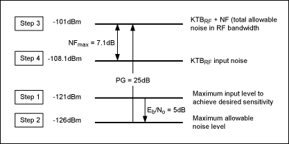
Sin = F × Nin × (Sout / Nout) Sin can be expressed as: Sin = F × KTBRF × Eb / No × 1 / PG is expressed in a more commonly used logarithmic form, taking 10 as the base for each item Multiply the logarithm of by 10 to get the unit dB or dBm. Then the noise figure NF (dB) = 10 × log (F), from which the following receiver sensitivity equation is derived: Sin (dBm) = NF (dB) + KTBRF (dBm) + Eb / No (dB)-PG ( dB) Digital example The following is an example of a base station receiver for a spread spectrum WCDMA cellular system. Although the receiver sensitivity equation is correct for input signals of various levels, for a given Eb / No, this example selects the maximum input signal power at the minimum sensitivity that satisfies the percentage of bit error rate (% BER). The conditions of this example are: For a digital voice signal with a rate of 12.2 kbps and a power of -121 dBm, the maximum specified input signal level must meet the minimum specified sensitivity of the system. For QPSK modulated signals, the specified bit error rate BER (0.1%) can be obtained when the Eb / No value is 5dB. The RF bandwidth is equal to the chip rate, which is 3.84MHz. KTBRF (log) = 10 × log (1.381 × 10⁻²³ W / Hz / K × 290K × 3.84MHz × 1000mW / W) = -108.13dBm. The specified user data rate Rbit is equal to 12.2kbps, PG is PG = Rchip / Rbit = 314.75numeric or 25dBlog. Take these values ​​and use the equation: Sout / Nout = Eb / No × Rbit / BRF to get the output signal-to-noise ratio: 5dB-25dB = -20dB. This means that the spread spectrum system with expanded bandwidth actually works under negative SNR. To obtain the maximum receiver noise figure (expressed as NFmax) that meets the minimum specified sensitivity, use the receiver sensitivity equation: Sin (dBm) = NF (dB) + KTBRF (dBm) + Eb / No (dB)-PG (dB) The following steps and Figure 2 show the specific method for obtaining NFmax:
Step 1: For the WCDMA system, the maximum specified RF input signal is -121dBm under the expected sensitivity.
Step 2: Subtract the Eb / No value of 5dB to get the maximum allowable noise level in the user band is -126dBm (12.2kHz).
Step 3: Add 25dB of processing gain to get the maximum allowable noise level within the RF carrier bandwidth of -101dBm.
Step 4: Subtract the maximum allowable noise level from the RF input noise to obtain NFmax = 7.1dB.

figure 2.
Note: If a more efficient detector is used in the receiver design, the requirement for the Eb / No value is only 3dB instead of 5dB, and the receiver sensitivity can reach -123dBm under the condition that the receiver NFmax is 7.1dB. In addition, because the requirements for the Eb / No value are reduced, while satisfying the maximum specified input signal of -121dBm, a NFmax value of up to 9.1dB is also tolerable. Summary Using the receiver sensitivity equation derived from the definition of noise figure, the designer can weigh and determine the receiver parameters in the spread spectrum link budget, which is feasible for any input signal level, so that this equation is used to determine the system Very practical in terms of sensitivity. Sin (dBm) = NF (dB) + KTBRF (dBm) + Eb / No (dB)-PG (dB) References CDMA Systems Engineering Handbook, Jhong Sam Lee & Leonard E. Miller, Artech House Publishers, 1998. CDMA RF System Engineering, Samuel C. Yang, Artech House Publishers, 1998.
PCB types can be also seperated according to it`s applications.Such as 3D Printer PCB,computer PCB,LED lighting PCB,automotive PCB,industrial PCB,etc.
Applications of Printed Circuit Boards
1. Lighting Applications
LEDs with aluminum-based printed circuit boards very desirable for a number of applications and industries.
2. Consumer Electronics
Consumer electronics are the devices we use daily, such as smartphones or computers. Even the newest models of refrigerators often include electronic components.
3. Medical Devices
For medical applications, a small package is needed to meet the size requirements for an implant or emergency room monitor.So medical PCB tend to be specialty high-density interconnect PCBs, also referred to as HDI PCBs. Medical PCB may also be made with flexible base materials, allowing PCB to flex during use, which can be essential for both internal and external medical devices.
4. Industrial Applications
5. Automotive Applications
6. Aerospace Applications
PCB Application
Custom PCB,PCB Application,Circuit Board Application,Printed Circuit Board Application
JingHongYi PCB (HK) Co., Limited , https://www.pcbjhy.com