Keywords: TMS320C32, PC, serial communication, code bit inversion
1 Introduction TMS320C32 (hereinafter referred to as C32) is a high-performance digital signal processor, it has a serial port on the chip, can achieve full-duplex serial communication, PC also has a serial communication interface, but two kinds of serial The communication protocol of the port is very different:
(1) C32 is synchronous mode, PC is asynchronous mode. The frame synchronization signal line of the C32 serial port is used separately from the data line. There are independent receiving frame synchronization FSR and sending frame synchronization FSX, independent receiving data line DR and sending data line DX; PC serial port has no separate frame Synchronization, data and synchronization are on the same signal line, and the receiving device relies on detecting the start bit to achieve synchronization.
(2) When C32 serial data is transmitted, the high bit of the byte is first and the low bit is behind, while the PC is low bit first and high bit second.
(3) When C32 data is transmitted, there is no start bit, and the PC has a start bit, a programmable stop bit and a check bit.
(4) C32 supports 8-bit, 16-bit, 32-bit serial data transfer, while PC supports 5-bit, 6-bit, 7-bit, 8-bit data transfer.
In some applications, when the C32 needs to communicate serially with a PC, the differences in these interface protocols will cause some trouble. Adding hardware circuits, such as TI's 16C754 chip, can directly implement protocol conversion.
In practice, I used the characteristics of the two to communicate, and designed a method for software to realize serial communication between TMS320C32 and PC. The implementation principle is described in detail below.
2 Serial communication conventions Serial communication conventions are:
Communication method: serial asynchronous. Interface mode: RS-232. Baud rate: 38400bit / s. Data character length: 8 bits. Start bit: 1 bit. Stop bits: 2 bits. No check digit.
3 Circuit connection C32 uses serial port 0, PC uses serial port A. The circuit connection of serial communication is shown in Figure 1.

In Figure 1, the abbreviations, names and definitions of communication signal lines are as follows:
TxD is Transfer Data, RxD is Receive Data, RTS is Request to Send, DX0 is data transmission, DR0 is data reception, FSR0 is data reception frame synchronization pulse, and GND is ground.
The Max232E in the picture is the inverter driver produced by Maxim, which is used to realize the level conversion. The TxD and RxD of the serial port of the PC are connected to the DR0 and DX0 of the C32 serial port 0 after level conversion. Here, the RTS (request to send) of the serial port of the PC needs to be level converted and connected to the frame synchronization pulse FSR0 of C32. The RTS generates the frame synchronization pulse signal required by C32 to receive.
4 Communication principle
4.1 TMS320C32 sends data to the PC. The data transmission from C32 to the PC is carried out on the DX1-RxD communication line. The operation steps of C32 are as follows:
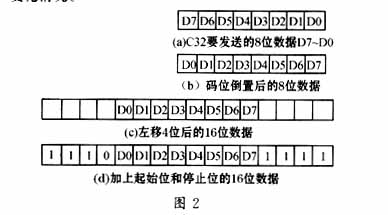
(1) Initialization; (2) Fetch data (see Figure 2a); (3) Invert the code of 8-bit data (see Figure 2b). The code bit inversion is because the C32 serial data is transmitted with the high bit first and the low bit back, while the PC is the low bit first and the high bit back; (4) Left shift by 4 and 16 bits, see Figure 2c; (5) Add start and stop bits, see Figure 2d. There is no separate frame synchronization for the serial port of the PC. Data transmission and synchronization are on a signal line. The receiving device synchronizes by detecting the start bit. Therefore, the start bit and the stop bit must be added; (6) Write data to Send data register; (7) Repeat steps (2) ~ (6) to send the next byte of data.
The data receiving program or process of the PC is the same as that of the conventional serial asynchronous communication, and does not need to be changed. The received data is the data sent by the C32.
Figure 2 shows the change of data bytes during the data transfer of C32.
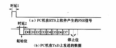

4.2 PC sends data to TMS320C32 When PC sends data to C32, it needs to generate a frame synchronization pulse signal FSR, which is sent by RTS of serial port (see Figure 1). When generating the FSR signal, two delays must be generated by software, delay 1 and delay 2. Delay 1 (see Figure 3a) ensures that the FSR pulse width corresponds to the baud rate. When the baud rate is 38 400bit / s, the time extension is about 26μs; Delay 2 (see Figure 3b) ensures that the FSR falling edge The time interval between the start bits of the transmitted data is equal to one bit. When the baud rate is 38 400bit / s, the elongation at this time is also 26μs. The operation steps of PC sending data are as follows:
(1) Initialization. (2) The software sets RTS = '1' to generate the rising edge of the FSR signal. (3) Software delay 1. (4) The software clears RTS = '0', and generates the falling edge of the FSR signal. Steps (2) ~ (4) generate a complete FSR pulse signal (see Figure 3a). (5) Software delay 2 (see Figure 3b). (6) Write data to the send data register. (7) Repeat steps (2) to (6) to send the next byte of data.
When C32 receives data, it first reads the received data register, and then performs shift and code bit inversion processing. The operation steps are as follows:
(1) Initialization. (2) Read the receive data register, 16-bit operation (see Figure 3c). (3) Right shift by 6 bits, valid 8-bit data is d13 ~ d6 (see Figure 3d). (4) The code bit is inverted, and the lower 8 bits of data are the data sent by the PC (see Figure 3e). (5) Repeat steps (2) to (4) to read the next byte of data.
When the PC sends data to C32, the corresponding relationship between the frame synchronization pulse signal and the transmitted data, and the data change process are shown in Figure 3.
5 Conclusion The software communication implementation method introduced in the concluding article only requires a small amount of software workload and no hardware circuit. The design principle is very simple, and the actual application also proves that this communication method is very reliable, which can be used for similar serial communication. .
references
Solar Stake Lights,Outdoor Stake Lights,Solar Garden Stake Lights,Outdoor Solar Stake Lights
Jiangmen Biaosheng Solar Energy Technology Co., Ltd. , https://www.bsprosolar.com