Design and Implementation of Ultra-Wideband Radar Signal Circuit
Abstract: The design and implementation of an ultra-wideband radar signal waveform generator is introduced. The signal is generated by DDS + PLL + mixer. The generator uses a high-performance digital phase-locked loop chip Q3236, voltage-controlled oscillator Q3500-0916T and mixer IAM-81008 to form the core unit, and uses a new low-frequency and ultra-wideband bandpass filter to complete the ultra-wideband radar signal. The realization of this ultra-wideband radar signal is of great significance for improving the performance of existing radars and developing a new generation of high-performance radars.
Keywords: UWB direct digital synthesis phase-locked loop mixer filter
Radar is an electronic device for radio detection, positioning, orbit measurement and identification of long-range targets. It occupies an important position for military and civilian use. The rapid development of radar technology has led to the continuous improvement of radar performance. As far as radar signals are concerned, it has been developed from traditional analog technology to digital technology. The traditional radar signal has only two forms of continuous wave and rectangular envelope RF pulse. Although the technology is mature, the radar using this signal has limited measurement capabilities and accuracy of target parameters, which is far from being able to meet the requirements of modern radar development. [1 ]. Based on this, this paper uses DDS + PLL + mixer + filter technology to design an ultra-wideband radar signal with wide frequency band, high stability and fast transition [2]. The realization of this ultra-wideband radar signal is of great significance for improving the performance of existing radars and developing a new generation of high-performance radars.
1 Preparation of the overall plan
The block diagram of the UWB radar signal circuit is shown in Figure 1. Its basic principle is to use the small frequency change of the reference source DDS [3 ~ 4] to excite the large-scale change of the output frequency f0 of the phase-locked loop. The specific formula is as follows: 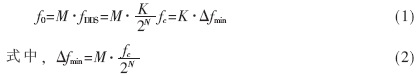
This article takes the generation of ultra-wideband signals from 160MHz to 650MHz as an example. The lower frequency input is generated by DDS, and the higher frequency output is generated by DDS + PLL + mixer. That is, the 3.3MHz DDS output signal is used to excite the PLL to generate 1160MHz ~ 1650MHz signal. This signal can be mixed with 1000MHz local oscillator to produce 160MHz ~ 650MHz signal (N = 32, M = 360).
2 Selection, design and simulation of unit circuits
The phase-locked loop is composed of Qualcomm's newly launched high-performance digital phase-locked loop chip Q3236, voltage-controlled oscillator Q3500C-0916T and suppression filter. The mixer uses HP's IAM-81008. The feedback amplifier in the amplifier uses a microwave monolithic integrated amplifier, using HP's INA-02186 silicon bipolar MMIC feedback amplifier; and the linear amplifier uses MC10H115, which is four amplifiers used for shaping and transmitting different signals through long lines. The local oscillator uses a crystal frequency doubling source, frequency doubling to 1000MHz, in order to reduce the output spur component of the frequency doubling source, filtering is performed at the output end to obtain a local oscillator source signal with pure spectrum. In order to shorten the frequency conversion time of the frequency synthesizer, a fast capture circuit is added on the basis of the phase locked loop. The fast capture circuit uses the frequency-digital conversion auxiliary capture method to obtain the capture.
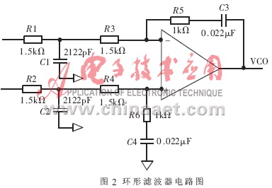
The loop filter in Figure 1 uses an active integration filter with pre-integration [1], as shown in Figure 2. 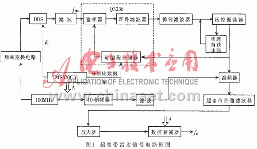
In terms of the steepness of the stopband attenuation, the elliptic function filter is the best, so the elliptic function filter is selected as the suppression filter. In this circuit, the reference input frequency is 10MHz and the reference frequency division ratio is 3, so the output of the frequency and phase detector is 3.33MHz. In order to reduce the spurious noise and phase noise of the entire frequency synthesizer, the design considers that the attenuation from 0 to 1.2MHz is not greater than 0.2dB, and the attenuation above 3MHz is greater than 60dB. As shown. Its amplitude-frequency characteristics are shown in Figure 4. 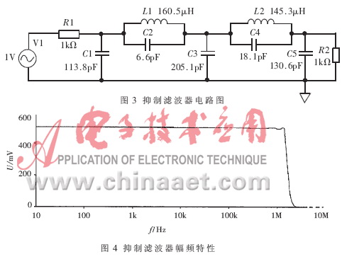
In order to achieve ultra-wide bandwidth, the 160MHz ~ 650MHz band-pass filter is designed with a capacitively coupled node coupling filter [5]. The designed filter circuit is shown in Figure 5. 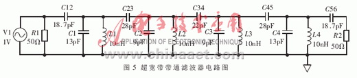
The designed band-pass filter is simulated with PSPICE, and its amplitude-frequency characteristics (V (R2)) are shown in Figure 6. 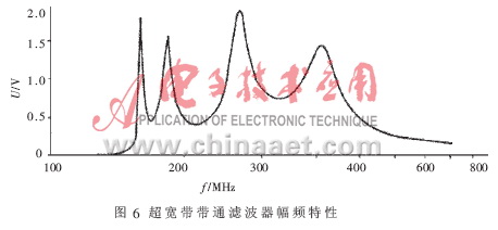
3 System connection and test
After the selection and design of the above unit circuit devices are completed, PROTEL is used for specific layout and wiring of the circuit board. In the process of wiring, pay attention to the power supply, the grounding of the device, and the shielding between the coupling devices. Finally, the signal generation results of the designed UWB radar signal generation circuit are simulated. The simulation results are shown in Figure 7. 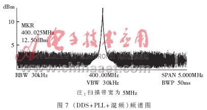
By analyzing the test results of the system, the final result of the circuit meets the requirements of various indicators within the expected signal form and operating frequency range.
The ultra-wideband and high-stability radar signal generation circuit is of great significance for improving the performance of existing radars and developing a new generation of high-performance radars. It not only enhances the radar's anti-jamming capability and effectively deals with missile radiation, but also has important applications in radar imaging, radar target recognition, radar low elevation tracking, etc. due to its relatively wide and absolute bandwidths; it is new The key technology of the first generation radar has wide application prospects.
Function: The LED Work Light has 1-5 modes;
Feature: The Led Work Light usually high power and super bright;
Trait: The products are waterproof, shockproof;
Method of application: Simple on/off push button operation;
Range of application: The LED Work Light for emergency events, camping, outdoor activities and indoor;
Adervantages: Our products are saled with factory price, and the quality can guarantee, lastly we provide warranty for 1 year.
LED Work Light
Led Work Light,Led Work Lamp,Portable Led Work Lights,Portable Work Light
Ningbo Henglang Import & Export Co.,Ltd , https://www.odistarflashlight.com