Application of current detection and measurement in automobile system
The design of modern automotive electrical systems is currently in one of the biggest changes in history. From revolutionary electric motor / generator hybrid electric propulsion and "fly-by-wire" power transmission devices to smart accessories for extended service life and increased efficiency (such as strapless pumps and LED lighting), etc. Integration into new vehicles. Users are increasingly expecting to have automated on-board diagnostic systems and predictive maintenance functions, which has also promoted the emergence of various new car body and engine management system designs. In many areas of such system redesign, an important information feedback is the current used by the special load. Current measurement is used to analyze whether the status is normal, and provides a basis for the implementation of fault protection and control rules. The basic change in this area is that intelligent and efficient "closed loop" designs are replacing traditional "open loop" systems in the past.
Basic current detection topology
Although non-contact current measurement can be achieved, this method generally requires high-cost instruments or expensive power supply unit products, so this method will only be used when costs and complexity allow it. In the automotive field, low cost is the key factor, so the detection resistance measurement method is the most suitable. Connect a small resistance detection resistance (in the order of milliohms) to the load, and measure the voltage drop on the resistance when supplying power to the load, you can accurately calculate the current value.
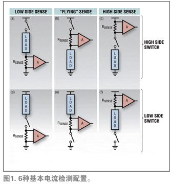
As far as the series connection of switches, loads and sense resistors are concerned, there are basically six different topologies, as shown in Figure 1 (a) to Figure 1 (f). These topologies can be classified as high-voltage switch or low-voltage switch based on the position of the switch relative to the load; and as low-voltage detection, "floating" detection, or high-voltage detection based on the position of the resistor relative to the power rail. Each solution may be the best solution for some specific applications. Another situation to consider is that when a fault occurs, the fault varies depending on the load characteristics. As a rule of thumb, people generally assume that the most likely failure is to connect to the frame (electrical ground), which is caused by the wrench touching the live bare terminal, or by the wire and the grounded metal parts Caused by contact. In this case, low-voltage end detection has inherent disadvantages. In most applications, the configuration of Figure 1 (c) is the preferred topology because it allows the switching and monitoring functions to be brought together, while maintaining a low number of connections.
Modern load and intelligent switch
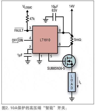
Since the introduction of power MOSFET devices, designers have regarded them as a potential replacement for relays. Modern N-MOSFET switches have on-resistance values ​​in the single-digit milliohm range, allowing the use of standard surface mount technology without awkward heat dissipation structures. Currently, low-cost integrated circuit solutions have been developed, which can provide self-contained boost gate drive functions. These circuits also use a fast failure protection mechanism so that the MOSFET will never be at risk of failure. Linear Technology's LT1910 is such a "smart switch" control integrated circuit. This device uses a low-resistance high-voltage current detection resistor (similar to Figure 1 (c)) to detect circuit overload and shut down the work before damage occurs MOSFET. As soon as the integrated circuit detects an overload condition, it sets a warning flag and periodically attempts to restart the load until the fault is cleared. Although this integrated circuit is only binary in nature, it is a good example in terms of using current detection to form a rugged "closed loop" electronic relay solution as shown in Figure 2.
Real-time current monitoring
In addition to providing intelligent switch protection for current detection, the signal on the detection resistor is allowed to be digitized after amplification and conversion, and the digitized signal is used as the "analog" feedback signal of the control loop. Current monitoring can reveal the working characteristics of many loads in real time. For example, the current consumed by the motor is proportional to its torque, so the trend of the frictional resistance of the bearing can be estimated, and the status of various starters can be detected without additional sensors. Other loads (such as lighting) are often driven in parallel by a common power source, so it is only a matter of accuracy to determine whether certain parts of the load fail to open when the life has expired.
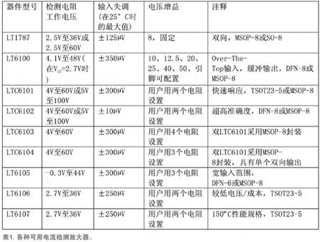
A particularly simple integrated circuit solution that achieves the above functions is a current-sense amplifier. Linear Technology ’s LTC6102 is an example of such an integrated circuit. The device is optimized for accurate unidirectional high-voltage automotive inspection. Figure 3 shows a typical circuit example using the LTC6102 to connect a general-purpose current-sense output to an analog-to-digital converter (ADC) input. Note that the output of the LTC6102 is current, so the reconstruction load (R2) can be placed at a distance from the integrated circuit without introducing ground loop errors. Due to the extremely high accuracy of this integrated circuit, even RSENSE values ​​below milliohms are practical, so heat and voltage losses are minimal. The added components D1 and R3 in this circuit provide power supply reverse transient protection. Table 1 lists some available sense amplifiers and their basic characteristics.
Factors to consider when using pulse modulated loads
As for the use of high-frequency pulse width modulation (PWM) technology to produce duty cycle modulated loads of variable performance levels, other factors must be considered when designing the current monitoring circuit. The main point is that the response time needs to be fast enough to respond to the fault condition at the turn-on portion of the waveform. Another point is that the switching action should not cause too much interference with the fidelity of the current reading. Normally, the configuration in Figure 1 (c) provides the best results again, because the impedance of this circuit is very low and the common mode problem is minimal. In the case where an average load current (DC component) is desired, post-filtering used in the analog or digital signal processing (DSP) field can be used to remove frequency components related to PWM. It is expected that the average power supply current value is related to the load current. This value provides a good indication of the subjective effect, regardless of the lamp intensity or starting power.
Monitor current of H-bridge driver
An H-bridge driver can be viewed as a pair of half-bridges that operate on complementary signals to produce a bidirectional differential output. Each half-bridge can be seen as an expansion of the unidirectional circuit of Figure 1 (c), that is, adding a low-voltage switch in parallel with the load on the configuration of Figure 1 (c). Figure 4 shows a circuit composed of an LTC6103. These two devices produce a differential output suitable for directly driving an ADC. Circuits like this are suitable for motors in mechanisms such as window lift, ambient atmosphere control, etc., and can perform reverse action no matter where they are.
Note that for load ground faults, the low-side MOSFET will not be subjected to excessive pressure, so monitoring each half-bridge on the high-side provides all the information needed. The load current can be determined by the difference between the unidirectional current readings of the two half-bridges. In addition, due to signed numerical control, when a high-voltage switch is turned on 100%, the load current can be accurately measured without duty cycle correction.
Conclusion
In the development of modern automobiles, electronic drive functions are increasing rapidly. Although an economical control design requires ruggedness, it adds a diagnostic function that monitors the load current in the system in a closed-loop manner. Regardless of whether the driver is single-ended or H-bridge, high-voltage current detection is the most practical way to implement the monitor function. The LT6100 series provides a wide selection of current-sense amplifiers. This series of integrated circuits can meet the specific needs of a variety of applications, such as composition accuracy / efficiency, operating voltage, high-temperature working monitoring solutions, and economical and practical high-voltage side monitoring solutions.
Touchless Sensor-Makes it germ Free
Environment Friendly-Prevents Contamination
Ideal fit for Kitchen/Bathroom/Bedroom
As users hands or debris enter the zone 6 inches (15cm) from the infrared sensor on top of the dustbin, the lid will automatically open.
The Lid will remain open if hand or debris is within the 6 inch (15cm) range of the infrared sensor. Lid will close 7 seconds after users hands move away.
The new touch switch panel has higher stability and efficiency. you can use it effortlessly. There are [OPEN" & [CLOSE" buttons for manual operation, and there is a ON/OFF power switch on the back of the dustbin.
The new removable plastic rim is easy to lift out, and the plastic ring helps leave no excess plastic bag visible (w/o liner).
Two liners (30L+20L) for easy recycling
Features:
-100% [Hands-Free" operation.
-[Germ-Free"-Prevents cross-contamination
- Trash Bag Retainer Ring stops full, heavy bag from falling in and keeps bag ends neatly out of view
-Rubber feet keeps this trash can in place and protects floors from scratches
-Removable hard ABS plastic head for easy cleaning
-Uses 4 AA-Sized batteries 1.5V(LR6) (Not included)
-Low energy-consuming
-Multiple colors to satisfy your different requirements.
-Capacity:30L+20L
-Dimensions: 34W x 48 L x 64H CM
-1 Year Manufacturer`s Warranty included
Rectangular Sensor Automatic Dustbin 2-Compartment 30L+20L
Automatic Dustbin,Hand Sensing Dustbin,Hotel Dustbin,Environmental Dustbin
NINGBO ZIXING ELECTRONIC CO.,LTD. , https://www.zixingautobin.com