CAN bus interface of absolute photoelectric shaft encoder
1 Introduction The absolute photoelectric shaft angle encoder is a digital angle measuring device that measures the angular position and angular velocity of the rotating shaft in real time. It converts the shaft angle information into digital codes in the form of degrees, minutes and seconds, and the Bus connection can realize real-time measurement. It has the advantages of high working reliability, strong anti-interference ability, high precision, power-off memory and so on. It is widely used in digital measurement tracking and positioning systems such as shooting range equipment, digital theodolite, radar and some large military equipment.
In these practical application control systems, due to the different data structures of the sensors and detectors of each subsystem, the absolute photoelectric shaft encoder will use different internal data communication methods, mainly including RS232, RS485 / 488 serial ports, parallel ports, etc. . However, in specific engineering applications, the above communication methods are often limited by transmission distance and communication rate. In recent years, serial communication has developed rapidly, and a variety of control system field bus forms have emerged. The CAN bus is one of the most widely used. It is the abbreviation of controller local area network bus and is an effective support for distributed control and real-time control. Serial communication network. Due to the high performance, high reliability and unique design of CAN bus, it has become the most popular and real-time field bus at home and abroad. The development and changes of internal communication methods in the control system make the encoder used to measure angular displacement and angular velocity provide a CAN bus interface to meet the fieldbus design requirements of the entire control system.
2 Encoder working principle and data transmission
2.1 Working principle The encoder consists of two parts: a data acquisition device and a data processing device. The structural block diagram is shown in 1. The single chip microcomputer is the core part of the encoder circuit system. After collecting the encoder signals (coarse code, medium fine code, fine code), it is subdivided by fine code, code channel correction, digital addition, electric zero adjustment, Software processing such as degree, minute and second conversion, and finally display and realize the interface with the control system.
2.2 Data transmission The data transmission between the encoder and the control system can be used in both parallel and serial modes. Parallel transmission transmits data through the parallel port. Each data requires one core of the data cable. For example, a 24-core cable is required for a 24-bit encoder. Therefore, the use space is limited, and it is only suitable for short-distance transmission and special requirements. occasion. In serial transmission, data information is transmitted serially through a twisted pair, and additional bits are added according to different communication protocols to implement functions such as error correction. This function can be extended to data bus systems. Serial transmission has fewer wires, less hardware, low cost, long transmission distance, and safe and reliable data.

2.3 Proposed encoder CAN bus interface In the comprehensive comparison of various field buses, the communication system based on CAN bus has many excellent characteristics: the data signal is transmitted by differential voltage; the bus transmission medium can use twisted pair, coaxial cable and Optical fiber; can work in multi-master mode, flexible communication mode; can transmit and receive data in point-to-point, point-to-multipoint and global broadcast mode; node information on the network can be divided into different priorities to meet different real-time requirements; non-destructive bus Arbitration technology; the data adopts short frame structure, each frame is 8Byte, and the data error rate is low; the MAC sublayer of the data link layer in the communication protocol has strict error detection capabilities; it has international standards and good openness. Therefore, in the transformation of the internal communication mode of the photoelectric tracking system, the CAN bus is used as the data communication bus structure, and then the encoder CAN bus interface is proposed.
3 Application of encoder CAN bus interface in photoelectric tracking system
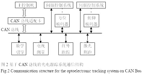
3.1 The encoder is used for the position detection of the photoelectric tracking system. The absolute photoelectric axis encoder is a sensor for measuring the azimuth and pitch angle of the photoelectric tracking system in the photoelectric tracking system. The internal bus structure of the photoelectric tracking system is transformed into the CAN bus communication method. The CAN bus interface has the characteristics of flexible interface and line saving. At the same time, it has a microprocessor and can be used as an intelligent node in the system to send remote frames directly to other devices to achieve intelligent control. Figure 2 is a communication structure diagram of the photoelectric tracking system based on CAN bus. The photoelectric tracking system uses a single serial bus structure of CAN bus instead of the parallel structure of multiple communication methods. The azimuth and pitch angles measured by the two photoelectric encoders are sent to the main control machine via the bus, and the main control machine processes the data accordingly. Through the bus control servo control system, all the sub-systems can be connected together by a pair of twisted pairs, which simplifies the system wiring, improves the overall system bus utilization, real-time data transmission and system scalability, and the bit error rate is greatly reduce.
3.2 Encoder node CAN bus interface hardware composition
The CAN bus interface is mainly composed of single chip microcomputer, CAN bus controller, CAN bus driver and photoelectric isolation hardware. The specific circuit of the CAN bus communication interface is shown in Figure 3.
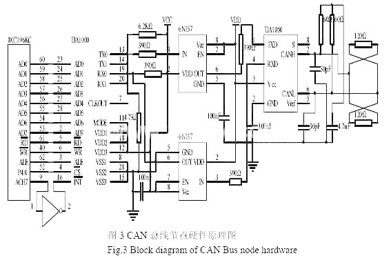
The single-chip computer selects Intel80C196KC, which is a 16-bit embedded microcontroller, which is more suitable for complex real-time control occasions. It is also responsible for the data processing of the encoder and the initialization of the CAN bus node. The CAN controller selects Philips Semiconductor's SJA1000 to realize the data communication interface between the bus and the host computer (control computer), supports CAN2.0A and CAN2.0B protocols, has an extended 64-byte receive buffer, and supports first-in first-out (FIFO) principle, support 11-bit and 29-bit identification codes, communication bit rate up to 1Mbps, can work in BasicCAN mode and PeliCAN mode. The CAN bus driver chooses Philips TJA1050, which is a high-speed CAN bus driver, which provides the interface between the CAN controller and the physical bus, realizes the differential transmission and reception functions of the CAN bus, and has a wide common mode range under strong electromagnetic interference Differential receiving capability, the input level is compatible with 3.3V devices, and unpowered nodes will not interfere with the bus. Joining TJA1050 can ensure high-speed data communication. For safety and improved anti-jamming capability, the use of TJA1050 good symmetric performance characteristics, use separate terminals. Two small capacitors of 30pF are connected in parallel between CANH and CANL and ground, which can filter out high frequency interference on the bus and a certain ability to prevent electromagnetic radiation. In order to further improve the anti-interference ability of the system, a high-speed optocoupler 6N137 is used between the CAN controller SJA1000 and the CAN driver TJA1050 to form an isolation circuit to achieve galvanic isolation. The power supply VCC and VDD on both sides of the 6N137 are completely isolated, which can prevent the circuit At the same time, two 120Ω bus impedance matching resistors should be connected at both ends of the bus.
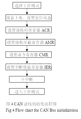
3.3 Node software design The angle information (degrees, minutes, and seconds) of the absolute photoelectric axis encoder is sent from the CAN controller to the CAN bus or from the CAN bus to the CAN receive buffer automatically by the SJA1000 bus controller. Its CAN bus interface communication program is composed of initialization subprogram, sending subprogram and receiving subprogram. First select the CAN bus working mode according to the actual system needs. Here, select the PeliCAN mode, 12MHz crystal oscillator, the bus data transmission rate is set to 500Kbits / s, each bus node should set the same data transmission rate to ensure normal communication. Determine that the physical connection between SJA1000 and the MCU is reliable, and then initialize the SJA1000 controller. In the SJA1000 reset mode, set the initial state of each register. The initialization flow chart is shown in Figure 4. The transmission and reception of data is accomplished by the sending subroutine and the receiving subroutine. The message ID determines the flow of node data. When sending data, the setting principle of the message ID reception flag bit segment is: the corresponding ID of the node that needs to be received The bit is 0 and the remaining bits are 1. When receiving data, it is the opposite. It is judged by ID whether it is information sent to itself. It is received, not filtered.
4 Conclusion
As a field-level communication bus, CAN bus has high reliability and cost performance. The absolute photoelectric shaft encoder with CAN bus interface makes it more flexible for use in control systems.
This article is innovative: the CAN bus interface of the encoder and its application in the photoelectric tracking system
Soundproof Weichai Diesel Generator
Soundproof Generator Box,Soundproof Weichai Diesel Generator,Weichai Soundproof Electric Water Diesel Generator,Soundproof Weichai Diesel Alternator
Jiangsu Lingyu Generator CO.,LTD , https://www.lygenset.com