The MAX6959 is a 4-bit, 9-segment LED driver that automatically scans and eliminates the jitter of eight key switches, and notifies the system processor to eliminate key jitter through an interrupt pin. Scanning function). The extended key scan scheme introduced in this article (from 8 keys to 12 keys) requires the addition of dual diodes on the additional keys.
Table 1. Standard 8-key connection for MAX6959 LED display driver
| INPUT1 | INPUT2 | |
| DIG0 / SEG0 | Key0 | Key4 |
| DIG1 / SEG1 | Key1 | Key5 |
| DIG2 / SEG2 | Key2 | Key6 |
| DIG3 / SEG3 | Key3 | Key7 |

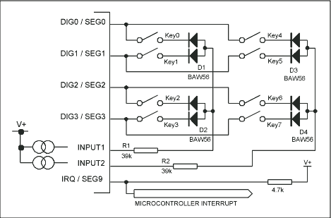
Figure 1. Standard 8-key connection of the MAX6959 LED display driver
Table 1 and Figure 1 show the standard 8-key connection of the MAX6959. The key switching circuit reads the state of 8 keys in a 2 x 4 matrix (2 columns, 4 rows). The four rows of the keyboard array are driven by four LED cathode driver outputs (DIG0 / SEG0 to DIG3 / SEG3). As part of the multi-layer LED drive, these LED cathode drive outputs are pulled to a low level of 320µs (nominal value) (sequential drive LED). These driver outputs are used to pull down one end of the key switch, and the other end of the key is connected to two input terminals: INPUT1 and INPUT2. These two input terminals are internally pulled to the high level V + of MAX6959. When the switch is pressed, INPUT1 or INPUT2 will be pulled to the low level by the corresponding DIG_ / SEG_ output. The MAX6959 detects the button and provides debounce for the button.
When multiple buttons are pressed at the same time, the diode in series with the switch can prevent two or more LED cathode drive output short circuit. For example, when Key0 and Key1 are pressed at the same time, the diode in series with the key can prevent DIG0 / SEG0 and DIG1 / SEG1 from being short-circuited, because at least one diode is reverse-biased under any circumstances. The diode uses a low-cost, common anode BAW56, SOT-23 package.
The MAX6959 judges the action of pressing or releasing 8 buttons at any time. The 8-bit register inside the device indicates the status of these 8 buttons. From this point of view, there seems to be no way to expand the scanning circuit in the design of the MAX6959. So far, everyone may have a feeling of being "deceived".
To be fair, we are exploring a redundant situation. In many applications, you only need to know whether a key is pressed. Usually, the situation where two keys are pressed at the same time is considered to be an incorrect key input, or to enter the factory diagnostic mode. This situation where two buttons are pressed at the same time is a "redundant" situation. We connect the four additional buttons as if a pair of buttons were pressed at the same time, as shown in Table 2. For example, when Key8 is pressed, for the MAX6959, the displayed state is the same as when Key0 and Key4 are pressed at the same time. As long as the physical positions of each pair of keys (such as Key0 and Key4) are not adjacent, this extended architecture can work effectively. The software design should ensure that the IRQ of the key is responded to within the minimum debounce period of 30.3 ms, and that each result corresponding to the key scan is properly analyzed and processed. If the software responds slowly to IRQ, it will be impossible to distinguish between the case of pressing two buttons at the same time (identifying the added button state) and the case of pressing the same two buttons in sequence. In either case, the key debounce register 0 x 08 will simply display each key position bit.
Table 2. MAX6959 LED display driver expanded 12-key connection
| INPUT1 | INPUT2 | INPUT1 and INPUT2 | |
| DIG0 / SEG0 | Key0 | Key4 | Key8 |
| DIG1 / SEG1 | Key1 | Key5 | Key9 |
| DIG2 / SEG2 | Key2 | Key6 | Key10 |
| DIG3 / SEG3 | Key3 | Key7 | Key11 |
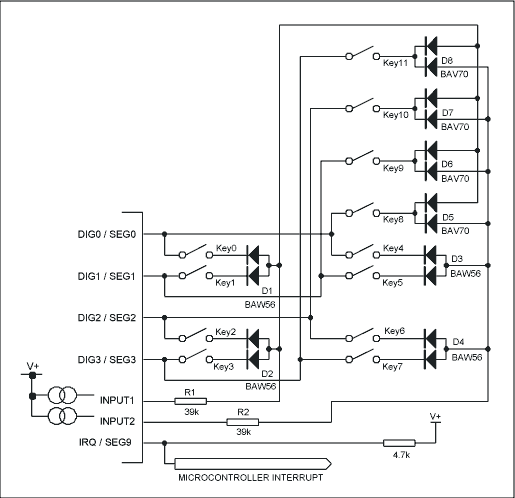
The circuit shown in Figure 2, each additional button requires a dual diode (such as low-cost, common cathode BAV70, SOT-23 package), when the switch is pressed, INPUT1 and INPUT2 are pulled down simultaneously.

Figure 2. MAX6959 LED display driver expanded 12-key connection
Finally, it is worth noting that the connection of the four additional buttons simulates the situation where two buttons are pressed at the same time. These two buttons are connected to an output of the four LED cathode driver outputs, DIG0 / SEG0 to DIG3 / SEG3. With this connection, each pair of keys always scans or debounces at the same time. If the two keys pressed at the same time simulated by the newly added keys are scanned by different LED cathode driver outputs, this way of working will be unreliable. Because key scanning is performed sequentially, two keys at a time, additional keys will miss the debounce period of one LED cathode driver, and debounce in another period. In this way, pressing two buttons at the same time will appear as pressing two buttons in sequence. The connection method recommended in this article can avoid this problem, because each pair of keys behaves as double keys debounce at the same time.
- Multiple Function Power Strip contribute you colorful and joyful experience while working or living with electronics.
- Power Strip with LED lamp, Extension Cord with Bluetooth Speakers, Electric Outlet Ultrasonic Mosquito Repellent, all our unique and patent design.
- Advanced flame-resisting materials. So it is safe and reliable with CE, ROHS and ETL certified. It brings more convenience in your life by stable circular base, you can charge your device more freely.
Multiple Power Strip, Multi-Outlet Power Strip, Extension Cord with Bluetooth Speakers, Multiple Function Power Strip, Electric Outlet Ultrasonic Mosquito Repellent
ZhongShan JITONGLONG Plastic Hardware Co. Ltd. , https://www.toukoo-electronics.com