1 The need for quantification and visual analysis
The museum belongs to one of the types of buildings that require relatively high light environment conditions. The lighting mainly needs to meet two requirements: visual clarity and comfort requirements and exhibit protection requirements. In order to satisfy the visibility of the exhibit and ensure the visual comfort of the viewer, it is necessary to control the brightness, brightness contrast, glare, light source color rendering index, color temperature and other parameters in the light environment. In China's museum lighting design specifications and other international standards, brightness and brightness contrast are commonly accepted parameter indicators to control exhibit performance and environmental glare.
For example, in general, the effective way to obtain brightness-related data is to perform physical physical testing using optical instruments. However, this method not only consumes time, but also is affected by the location and number of test points. For this reason, the non-measured quantitative analysis system has been gradually developed and applied, mainly including image analysis of MS Rea, CAPCALC of Steven J. Orfield, CCD digital camera test of V. Berruto, and SM image measurement system of Tianjin University Shen Tianxing. . The limitations of these system applications are mainly due to the high cost of the device, the complexity of the application or the numerical accuracy. With the gradual advancement of HDR (High Dynamic Range) image technology, in 2005, Lawrence Berkeley National Laboratory improved and evaluated this technology mainly used in computer graphics and image capture, and transferred to the architectural light environment. Analysis of the application. Subsequently, with regard to the insertion of auxiliary functions such as alignment, automatic reading, and superimposed brightness response curves of digital images captured by digital cameras, the free technology platform is now being analyzed and expanded in many lighting research institutions.
2 HDR image technology principle
The first way to propose HDR images was Paul Debevec, who published an article at the 1997 SIGGRAPH conference on how to recover high dynamic range images from a set of photos of the same scene under different exposure conditions. This technique can be captured by a camera. An image that achieves a larger dynamic range from dark shadows to brighter sources. The essential reason for this technology is that most digital cameras, including display instruments, can only display or capture brightness changes of several orders of magnitude, while the actual scene brightness range can reach 12 to 14 orders of magnitude under human eye conditions. Therefore, when the brightness contrast range exceeds the range that can be represented by the single image digital information, the data will overflow and cause the actual information of the environment to be missing. If the increase or decrease in exposure meets local environmental details, it will affect other parts to create an exposure transition or complete darkness (Figure 1). Therefore, after synthesizing a high dynamic range (HRD) image through a low dynamic range (LDR) image, the Tone Mapping technique is used to approximate the final image on a limited dynamic range medium such as a computer monitor or a printed image. HDR image. Although the HDR image displayed on a medium such as a screen does not fully reflect the brightness contrast relationship, the file itself has relatively accurately recorded the brightness and brightness relationship information of the scene, which provides conditions for analysis and evaluation of illumination by a digital camera. The storage format of HDR images can be selected for different types of applications and computer systems, including RAW, Radiance, TIFF, JPEG, etc. Table 1 shows the compression degree and file size of the data contained in each type of captured image of the same scene.


3 HDR image technology application process
Due to the convenience and accuracy of HDR image technology, it is relatively easy for architects to apply in a three to four step process in their design work. For professional light environment analysis, the application process of HDR technology can be further subdivided into five steps: determination of brightness response curve, acquisition of multi-exposure time scene image, HDR imaging, scale calibration and image analysis.
1) Determination of the brightness response curve: due to different models of cameras
The response to brightness is different, and the pixel brightness in the image obtained by the same model camera is not linearly related to the actual brightness. Therefore, the correspondence between the brightness of the camera digital image and the actual point brightness in the scene can be restored by determining the brightness response curve. relationship. The specific method is to take a group of photos with a wide range of exposure, and import them into HDR Shop or Photosphere software to get the “brightness response curve†(Figure 2).

2) Acquisition of multi-exposure time scene image: The scene image is collected by adjusting the different exposure amount by the digital camera, and the details in the space to be analyzed are completely reflected as much as possible, so that the obtained photo is the original LDR (Low Dynamic Range). image.
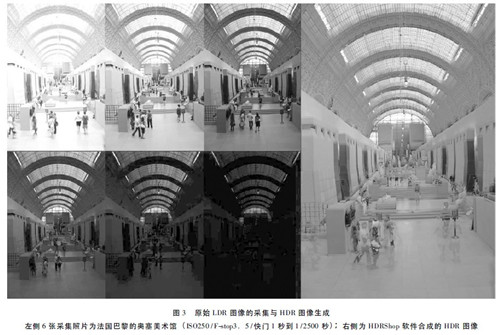
3) HDR imaging: Import LDR images in software such as HDR-Shop or Photosphere, and superimpose the brightness response curve to generate HDR images. Currently, a wide variety of HDR imaging software has been developed, some of which are free to use, such as MAC-based Photosphere, PC's HDRShop software. Figure 3 shows an HDR image obtained by overlaying a set of LDR images by HDRShop.
4) Photometric Calibration: First, the camera aperture is sized by the aperture in the lens. The aperture value is transmitted to the body through the aperture lever or contact. The construction is only a limited number of complete repeats, so each The actual aperture size will be different when the image is acquired, which will bring some errors. In addition, there is a certain error between the shutter speed indicated on the camera and the actual exposure time, such as a shutter speed of 1 / 500s, which is 1 / 531s on the Nikon F3. These errors add up so that the camera's exposure is not completely accurate. However, the image exposure involved in HDR technology comes from the parameters displayed by the camera, so its pixel brightness only adjusts the error of the overall sensitivity of the camera's photosensitive device after superimposing the brightness response curve, and cannot change the brightness of the individual pixel brightness of the HDR image. Sex. This requires us to use the actual brightness tester for the same position correction. The ratio of pixel brightness to actual brightness is also called the calibration factor.
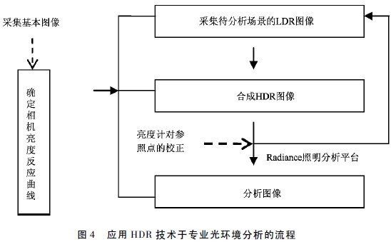
5) Image analysis: The HDR images obtained after correction can have various formats as shown in Table 1. These digital images can be used for analysis of pseudo color maps and iso-brightness graphs in HDR-Shop, Photosphere. In addition, Radiance XYZE format can also be used for analysis in Radiance professional lighting analysis software to obtain human conditional images, luminance grayscale images, and the like. Figure 4 shows the entire analysis process using HDR image technology in conjunction with the camera.
4 Verification of HDR technology application in museum light environment
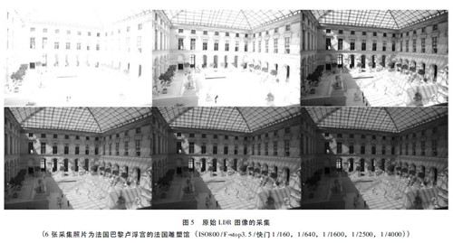
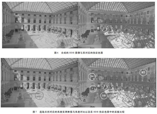
The above mentioned the uniqueness of the indoor light environment of the museum building, so in this topic we also selected the French sculpture exhibition hall in the Louvre building in Paris as the application object and verified the numerical accuracy, and adopted the Minolta LS-100 brightness. The measured brightness is measured. First, we used the camera Nikon D80 to capture six different exposures of the space in Figure 5. The HDR image was generated using MacPhotosphere (Figure 6 left) and the following pseudo-color image was obtained (Figure 6 right). For the accuracy of the brightness values ​​of HDR technology, we use the method of synchronous physical testing to compare. The left side of Figure 7 shows the brightness value corresponding to the selected point in the actual place and the brightness contrast value (in the lowest brightness point unit); Figure 7 shows the corresponding HDR pseudo color image brightness contrast on the right side.
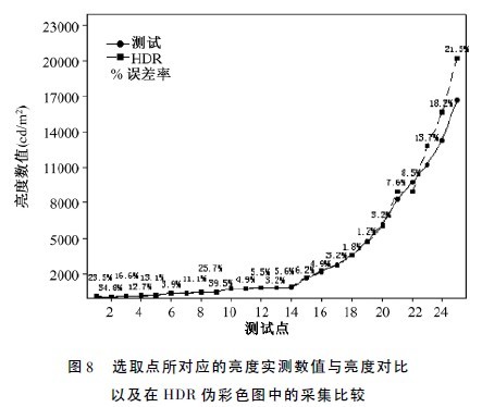
We used the same method to collect and analyze images of a total of five sets of building light environments and performed simultaneous brightness measurements to obtain the following graph 8. 9%, and the average error after the statistics is 7.9%, and the brightness is changed from 13.2 to 16676. 5cd / m2, and the average error after the statistics is 7.9%, and the image is collected and tested in a clear sky. High errors are mainly distributed in areas that are too bright and too dark. The HDR image after the scale correction by the actual measurement will have more accurate brightness information.
For the accuracy of the application of this technology, Dr. MN Inanici has done a comparison of HDR image analysis and physical test of the same scene. He uses Nikon CoolPix 5400 and FC-E9 fisheye lens to obtain images and export HDR images with brightness values ​​and 2%。 Under the natural light conditions of 7.2%. In addition, because the camera reacts differently to different levels of color, different light source conditions can affect the brightness value of HDR. The averaging of the average brightness error is 7.3%, based on the 485 point-to-point comparisons under different natural light conditions.
5 Applicability discussion
The application and development of HDR technology provides lighting researchers with a relatively accurate, low-cost and fast digital analysis approach, while meeting regional brightness assessments that are not possible or accurate in field testing. Moreover, HDR technology can be combined with the DesktopRADIANCE lighting analysis platform for more detailed analysis of synthesis, equal brightness curves, brightness contrast and more. We believe that with the improvement and development of digital image technology, HDR technology has great potential in the field of lighting research. At present, the Institute of Building Technology of the School of Architecture, Tianjin University, based on the results and technical principles of the original SM image measurement system, attempts to use the camera to obtain the principle of point illumination combined with the material reflectivity to generate the illumination distribution map, further considering the irradiance. The parameters are obtained; in addition, the key spectral intensity distribution is obtained for the original red, green and blue three-color channels of the HDR image. The technology platform can be applied to the study of phototropic animal and plant light ecology and green lighting. With the development of digital camera technology, such as photo overlay function, alignment function, fisheye lens marking function, and the manufacturing technology of digital camera mechanical components, the method based on HDR image technology has a broad field in related lighting. Application prospects.
Here you can find the related products in LED Pendant Light, we are professional manufacturer of Cylinder Led Pendant Light,Led Pendant Light, Round Ball Light ,Led Pendant Luminaires. We focused on international export product development, production and sales. We have improved quality control processes of LED Pendant Light to ensure each export qualified product.
If you want to know more about the products in LED Pendant Light, please click the product details to view parameters, models, pictures, prices and other information about Cylinder Led Pendant Light,Led Pendant Light,Round Ball Light,Led Pendant Luminaires.
Whatever you are a group or individual, we will do our best to provide you with accurate and comprehensive message about LED Pendant Light!

LED Pendant Light
Cylinder Led Pendant Light,Led Pendant Light,Round Ball Light,Led Pendant Luminaires
Guangdong Decosun Lighting Technology Co.,Ltd , https://www.decosun-lighting.com