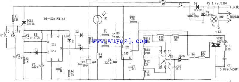
As shown in the diagram, this is an "empty city meter" anti-theft alarm system. The term "empty city meter" refers to a setup that automatically turns on lights when the house is unoccupied or during duty hours, especially after dark. If someone breaks in through the door, the system triggers a delayed alarm. The circuit includes a monostable delay circuit (IC1), a light-controlled multivibrator (IC2), a step-down rectifier power supply, and a thyristor trigger circuit.
The power supply for the delay circuit (IC1) is controlled by a thyristor, SCR1. The platen switches K1 and K2 control the on/off state of SCR1. Under normal conditions, the contacts of these switches are closed, allowing R1 and C1 to charge. When someone enters, the switch contacts open, activating the gate (G) of SCR1, which turns it on. This powers the delay circuit IC1.
At the moment SCR1 turns on, the voltage across C2 and C3 cannot change instantly. Therefore, the trigger pin (pin 2) of the 555 timer remains high, and the circuit does not activate immediately. As C2 and C3 charge, the voltage at pin 2 gradually drops. Once it falls below 1/3 VDD, the 555 timer flips, and its output (pin 3) goes high. This initiates a 20-second delay. During this time, diodes D1 and D2 turn on, triggering the buzzer, while IC2 starts oscillating and intermittently activates SCR2, causing the light to flash.
After about 2 minutes, the capacitor C2 continues charging. When the voltage on C3 exceeds 2/3 VDD, IC1 resets, and pin 3 returns to a low level. This turns off D1 and D2, stopping the alarm and turning off the light. The system then waits for the next trigger.
In addition, the multivibrator IC2 is sensitive to ambient light. A photoresistor (R7) controls the circuit. During the day, R7 has low resistance, keeping the voltage at pin 6 above 2/3 VDD, so IC2 remains in reset mode with a low output. At night, R7’s resistance increases, lowering the voltage at pin 2 below 1/3 VDD, which causes IC2 to start oscillating. This triggers SCR2, turning on the light. When the photoresistor is exposed to light again, the resistance drops, raising the voltage at pin 2 above 2/3 VDD, which resets IC2 and turns off the light. This cycle creates a flickering effect, making the system more effective at deterring intruders.
Advantages of overloaded connectors:
1. Pre-installation, pre-installation of a large number of complex circuits can greatly improve the efficiency of equipment installation and reduce the rate of wiring errors.
2. The heavy-duty connector provides a highly integrated connection, which improves the effective utilization of equipment space.
3. Easy to connect. Efficiently realize the modular structure of each functional template of the equipment, which is convenient for equipment transportation, installation and maintenance. The connector is widely used in the field of power transmission and distribution.
4. The high protection level (IP65.IP68) provided by the heavy-duty connector has incomparable advantages for equipment connection systems in harsh environments. Provide effective protection in harsh environments such as dust, rain, cold, ice and snow, and oil.
Hsb Series Connector,High Current Heavy Duty Connector,35A Heavy Duty Connector,Machine High Current Connector
Kunshan SVL Electric Co.,Ltd , https://www.svlelectric.com