0. Introduction
With the rapid advancement of modern technology, high-tech products have become an essential part of daily life due to their compact size and ease of use. The "shake stick" offers a unique and refreshing way to transmit information through simple motion, making it ideal for social events, parties, and entertainment programs. This device not only enhances user experience but also opens new possibilities for visual communication.
This article presents a creative design of an electronic device known as the "shake stick." It uses 16 pre-programmed sequences to control 16 LEDs, displaying text and simple graphics based on the movement of the user's hands. The system is built around the AT89C51 microcontroller, which manages the LED array. A ball switch detects the shaking motion, and the microcontroller adjusts the refresh rate of the LEDs accordingly. By leveraging the human eye’s persistence of vision, the device creates a smooth visual display that appears to move with the shake, effectively conveying information in a visually engaging manner.
1. Hardware System Composition
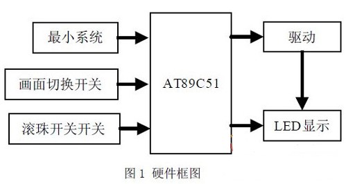
The LED "shake stick" is an electronic device based on single-chip microcontroller technology. It features a clear screen with buttons for switching between different displays. The system consists of three main parts: the microcontroller control unit, the LED driver circuit, and the LED display module. A block diagram of the hardware structure is shown in Figure 1.

1.1 Button Module
The device uses a screen change switch to toggle between different display modes. A ball switch is used to detect the direction of the shake, allowing the device to display specific content when shaken in a particular direction. If the device is not shaken properly, ghosting or mirrored images may appear. Mercury switches are more stable but less safe, while ball switches are safer and more durable. Although slightly less stable, they can be compensated for by software. A manual reset button is included to start or stop the system.
1.2 Control Unit
The microcontroller serves as the central control unit of the system. It manages the brightness and display of the LEDs. The display effects are programmed using software and external interrupts, allowing for dynamic and responsive visual output.
1.3 LED Display Module
The display section of the device is designed based on the principles of an LED dot matrix. The display process involves either row scanning or column scanning. In column scanning, the font data is input through the row driver, and each column is scanned sequentially. When a column is at a low (or high) level, and the row is at a high (or low) level, the corresponding point is activated. The design of the LED display stick follows a similar principle, treating the stick as a single column in a dot matrix. To ensure clarity, 16 high-brightness LEDs are arranged in a straight line, forming a 16-row by 1-column display. Data is transmitted using column scanning. When the device is shaken, the principle of visual persistence allows the illuminated column to appear continuous, creating a moving visual effect. As long as the shaking speed exceeds the minimum visual persistence time, the image remains visible, enabling the device to "swing" out patterns effectively.


Car Antenna Adapter,Din Motorola Plug Connector,Din Plug Cable Connector,Din Crimp Cable Connector
Changzhou Kingsun New Energy Technology Co., Ltd. , https://www.aioconn.com