The principle of the Hall effect
The Hall effect is a kind of magnetoelectric effect. This phenomenon was discovered when Hall (AHHall, 1855-1938) studied the conductive mechanism of metal in 1879. Later, it was found that semiconductors, conductive fluids, etc. also have this effect, and the Hall effect of semiconductors is much stronger than that of metals. Various Hall elements made by this phenomenon are widely used in industrial automation technology, detection technology, information processing, etc. aspect. The Hall effect is the basic method for studying the properties of semiconductor materials. The Hall coefficient measured by the Hall effect experiment can determine important parameters such as conductivity type, carrier concentration, and carrier mobility of the semiconductor material. The Hall effect in fluid is the theoretical basis for studying "magnetic fluid power generation". According to the principle of Hall effect, the magnitude of the Hall potential depends on: Rh is the Hall constant, which is related to the semiconductor material; IC is the bias current of the Hall element; B is the magnetic field strength; d is the thickness of the semiconductor material. For a given Hall device, Vh will depend entirely on the measured magnetic field strength B.
A Hall element typically has four terminals, two of which are the input of the bias current IC of the Hall element and the other two are the output of the Hall voltage. If the two outputs form an outer loop, a Hall current is generated. In general, the setting of the bias current is usually given by an external reference; if the accuracy is high, the reference is replaced by a constant current source. In order to achieve high sensitivity, some Hall elements are equipped with permalloy with high permeability. The Hall potential of these sensors is large, but saturation occurs around 0.05T, which is only applicable to low limits. Use in a small range. In recent years, various types of new integrated Hall elements have emerged due to the rapid development of semiconductor technology. Such components can be divided into two categories, one is a linear component and the other is a switch component. Principle of linear Hall elements:
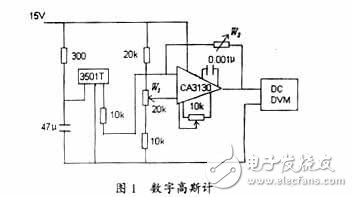
UGN350lT is a commonly used three-terminal linear Hall element. It consists of a voltage regulator, a Hall generator and an amplifier. With the UGN350lT, it is very convenient to form a Gauss meter. Its use is very simple, first make B=0, record the value of VOH in the table below, then stick the probe end face on the object to be tested, and record the new indication value VOH1. ΔVOH=VOH1-VOH, if ΔVOH “0â€, it means that the end face of the probe is measured as N pole; otherwise, it is S pole. The sensitivity of the UGN3501T is 7V/T, so that the corresponding measured magnetic induction B can be measured. If a digital voltmeter (DVM) is used, the linear Gauss meter shown in Figure 1 can be obtained. The op amp uses the high-precision op amp CA3130. The specific zero adjustment mode of the circuit is: after turning on the power, let B=0, adjust W1 to make the value of DVM zero, and then attach a standard bismuth aluminum boron magnetic steel (B=0.1T) to the end face of the probe. Adjust W2 so that the DVM can be displayed as 1V. If the indication value of the Gauss meter is -200mV, the end face of the probe is detected as the S pole, and the magnetic field strength is 0.02T. The Gauss meter can also be used to measure alternating magnetic fields, but the DVM should be changed to an AC voltmeter. It is obvious that the function of the conventional digital multimeter can be easily extended by using the circuit of Fig. 1.
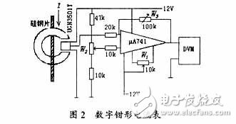
The UGN3501T can also be used to form a clamp-type ammeter as shown in Figure 2. The Hall element is placed in the gap of the clamped cold-rolled silicon steel sheet. When a current flows through the wire, a magnetic field is generated in the clamp ring, the magnitude of which is proportional to the number of ampoules flowing through the wire current; this magnetic field Acting on the Hall element, the corresponding Hall potential is induced, and its sensitivity is 7V/T. After the op amp μA741 is zeroed, it is linearly amplified and sent to the DVM to form a digital clamp-type ammeter. The debugging of this table is also very simple: when the current in the wire is zero, adjust W1 and W2 to make the value of DVM zero. Then input 50A of current, adjust W3 to make DVM read 5V; reverse input -50A current, the number indicates -5V. Repeatedly adjust W1, W2, W3, the reading can meet the requirements. This clamp-type ammeter has been tested and its sensitivity is not less than 0.1V/A. Similarly, this ammeter can also be used for AC current measurement. It is convenient to replace DVM with AC voltmeter.
Honeywell sensor applications and applications in the electric bicycle industry
Hall sensors are used in a wide range of applications, including aerospace technology, medical technology, transportation, industry, and measurement and testing. At present, the field of electric bicycles is active in the field of application. All of this is due to Honeywell's high-quality four-Hall components. Other high-sensitivity Hall-effect latches use dual-Hall or single-Hall components, which makes it very sensitive to package stress, while Hall elements make these sensors more stable and excellent. These new high sensitivity latches are specifically designed for brushless DC motors. It features a wide temperature range, high sensitivity, compact design (available in SOT-23 and TO-92 packages), and bipolar latched magnetic components that maintain performance over the entire operating temperature range. Stable), wide voltage range, built-in reverse voltage capability, ROHS-compliant materials, all of which are important for brushless current motors in a variety of industrial applications. Honeywell sensors are equipped with reliable high magnetic sensitivity switching points and no chopper stabilization technology is used on their Hall elements. These features of Honeyley enable the sensor to output a complete signal and reduce the latch response time to 20 microseconds.
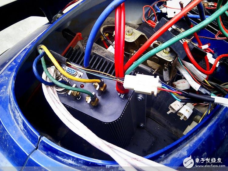
Electric vehicle control experiment diagram
Hall sensor for electric vehicle speed control
As the name suggests, the speed control is a speed control component of an electric vehicle. This is a linear speed control component with many styles but the same working principle. It is generally located on the right side of the electric vehicle, in the direction of the right hand when riding, and the rotation range of the electric vehicle handle is between 0 and 30 degrees. The signal characteristics of the handle and the brake lever: the form of the handle, the signal characteristics and the signal restructuring.
The electric car's handle has three leads: the power supply (thin red +5V), the ground wire (fine black), and the speed control signal line (linear continuous change signal fine green). There are two types of handles used in electric vehicles: photoelectric switch and Hall switch. At present, the majority of electric vehicles adopting the Hall switch. Common linear Hall components are: AH3503 AH49E A3515 A3518 SS495 For example: AH3503 linear Hall circuit consists of voltage regulator, Hall voltage generator, linear amplifier and emitter follower, the input is magnetic induction, output is and input The amount is proportional to the voltage. The quiescent output voltage (B = 0 GS) is about half of the supply voltage. When the S magnetic pole appears on the Hall sensor marking surface, the drive output is above zero level; the N magnetic pole will drive the output below zero level; the instantaneous and proportional output voltage levels determine the magnetic flux density of the most sensitive surface of the device. Increasing the supply voltage increases sensitivity. Product features: small size, high precision, high sensitivity, good linearity, good temperature stability and high reliability. The magnitude of the output voltage of the Hall switch depends on the strength of the magnetic field around the Hall element. Rotating the handle changes the strength of the magnetic field around the Hall element, which in turn changes the output voltage of the Hall handle.
The signals of the Hall switch used on the electric car are as follows: the output voltage of the type of the switch, the power supply is 5V, the power supply is 5V, and the single-Hole switch is 1.1-4.2 (maximum) /4.2- 1.1 (small amount); single holster transfer 2.6-3.7 (very few) /3.7-2.6; single holster transfer 1-2.5/ 2.5-1; single holster transfer 2.5-4/4-2.5; Ear turn 0-5/5-0; photoelectric turn 0-5 (small) / 5-0. The most commonly used ones are the following two kinds of signal transfer: 1-4.2V (commonly known as positive), 4.2-1V (commonly known as reverse). Among the two types of signal transfer, the 1.0V to 4.2V transfer is the majority. Other output voltage switches, which are currently rare in the market, have become non-standard products in fact, and such non-standard switches have been used more in early electric vehicles. Therefore, most of the controllers currently on the market are products that recognize the 1-4.2V switch signal. When the handle or controller of the electric vehicle needs to be repaired and replaced, once the switch signal does not match the controller, it is necessary to modify the switch so that its output signal can match the controller. Reconstruct the output signal: Disassemble the rotary handle and change the polarity of the magnetic steel working surface inside the rotary handle to change the potential of the rotary output. If there are two magnetic steels in the handle, turn the two magnetic steels 180° and reinstall them. If there is only one magnetic steel in the transfer, take out the magnetic steel, reverse the 180°, and install the handle. This changes the starting position of the working magnetic field of the Hall element inside the turn, thereby realizing the transformation of the output signal of the turn. A mechanical switch button is added to the handle of the lock handle, which can be used as a mode switch button under the control of the controller for mode conversion of 1:1 assist, electric, fixed speed and fault self-test.
Hall sensor for electric brake lever
The turn signal is a drive signal for the rotation of the electric vehicle motor, and the brake signal is a brake signal for the motor to stop rotating. The electric vehicle standard requires that the electric vehicle should automatically cut off the power supply to the motor when the electric brake is braked. Therefore, there should be a brake lever position sensing element on the electric brake lever. When the brake brake is actuated, the brake signal is transmitted to the controller, and the controller stops the power supply to the motor immediately after receiving the brake signal.
The position sensing elements of the electric brake lever are mechanical micro-switches (both mechanical normally open and mechanical normally closed) and switch-type Hall sensing components (two types of brake low potential and high brake potential). The mechanical switch type has two leads, one for the negative pole and the other for the low-voltage brake controller. For a controller that supports a high-level brake, one is connected to +12V, and the other is connected to the wire. The three types of Hall-type lead wires are: brake line (thin blue +5V), negative pole (fine black), and the remaining one is broken wire. Common unipolar switching Hall element models are available in AH41/ AH3144/ A3144/ A3282.
Generally, the normally open brake signal is a normally high potential. When braking, the micro switch inside the brake is closed and its signal becomes low. Generally, the normally closed brake signal is a normally low potential. When braking, the micro switch inside the brake is opened and its signal becomes high. Generally, the brake signal of the electronic low-potential brake is a constant high potential. When braking, the Hall element signal inside the brake is turned over, and the signal becomes low. Generally, the brake signal of the electronic high-potential brake is a constant low potential. When braking, the Hall element signal inside the brake is turned over, and the signal becomes high. The change of the high and low potential of the brake signal is that the controller recognizes whether the electric vehicle is in the braking state, thereby judging whether the controller supplies power to the motor. When the brake lever or controller of the electric vehicle needs to be repaired and replaced, it will encounter the situation that the brake lever signal does not match the controller. This requires the brake lever to be modified so that its output signal can match the controller. Therefore, in the maintenance practice, regardless of the form of the brake lever and regardless of the brake signal recognized by the controller, it is necessary to appropriately improve various types of brake signals to match the signals that the controller can recognize.
Rental Screen also known as Mobile LED Display, divided into outdoor mobile screen and indoor mobile screen. Inside and outside rental screen are thin, strong weather resistance die-cast aluminum cabinet, and the use of the latest anti-collision disc technology, enhance the transport and installation of the anti-collision strength of the screen, extend the service life. The protection level of outdoor rental screen is higher than that of indoor rental screen, and the IP level is higher than IP65.

The screen adopts seamless assembly technology, screw, magnetic absorption coexistence, simple installation and maintenance, to ensure the flatness of the screen body. Hoisting, landing, wall hanging, lying flat (floor tile), straight spell, arc spell and other installation methods, to meet the needs of customers on different site locations.
Mobile screen PH2.97/PH3.91/PH4.81 as a mobile rental use, very popular with customers. MobileLED Display is widely used in Mobile Performance.Equipment Leasing.Information Release.Event.Choreography etc.

LED Wall Rental Screen,Mobile Video LED Display,Advertising Screen
Shenzhen Vision Display Technology Co,.LTD , https://www.ledvdi.com