1 Introduction
The substrate integrated lens antenna array integrates the antenna array on the back surface of the substrate lens, and the antenna array elements can have different forms, such as a patch antenna, a slot antenna, and a butterfly antenna. The antenna array can be either a line array or an area array. The electromagnetic wave from the target passes through the objective lens and then converges on the antenna array through the substrate lens. The substrate integrated lens has the advantages of eliminating the surface wave of the microstrip antenna and increasing the mechanical strength, and has been widely used in the millimeter wave band.
Compared with the conventional substrate integrated lens, the microlens array has the following advantages: reducing the mutual coupling between the array elements, improving the resolution of the imaging system, leaving more space for the subsequent circuits. In this paper, microlens arrays are applied to millimeter-wave focal plane array imaging. In addition to conventional refractive microlens arrays, a diffractive microlens array that is easy to process is proposed.
2 light path diagram
The combined optical path of the optimized objective lens and the refractive microlens array is shown in Fig. 1. Assume that a line of polarized waves is at an angle ![]() It is incident on the objective lens, concentrated by the optimized objective lens, and then condensed by the microlens to finally converge on the focal plane of the microlens. In Figure 1, the angle of incidence
It is incident on the objective lens, concentrated by the optimized objective lens, and then condensed by the microlens to finally converge on the focal plane of the microlens. In Figure 1, the angle of incidence ![]() Separately
Separately ![]()
![]() with
with ![]() As can be seen from the figure, the incident waves at different angles finally converge on the focal plane of different microlenses.
As can be seen from the figure, the incident waves at different angles finally converge on the focal plane of different microlenses.
The objective lens parameters are the same as in the literature [5]: diameter is 124mm, focal length is 206.5mm, and refractive index is 1.449 (Teflon). The microlens is a Teflon extended hemispherical lens with a radius of 4.5 mm and an extended length of 5 mm. The center spacing of two adjacent microlenses is 10 mm. The incident wave frequency is 94 GHz.
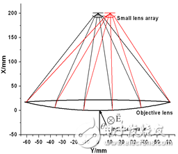
Figure 1 Optimized objective lens and refractive microlens combined optical path diagram
3 CST simulation analysis
The diffractive microlens and the feed antenna are shown in Figure 2. Figure a, the diffractive microlens consists of a dielectric base and two cylinders. The radius of the cylindrical body is designed such that the incident wave can be diffracted after reaching the diffractive lens and finally converge to the center of the microlens. Finally, the calculated height of the medium base is 5 mm, and the radius of the large and small cylinders is 4.5 mm and 3.0 mm, respectively. The feed antenna is a rectangular microstrip patch antenna, and the dielectric substrate is a Duriod 5880 having a thickness of 0.127 mm and a dielectric constant of 2.2.

(a)

(b)
Figure 2 Diffractive microlens and feed antenna
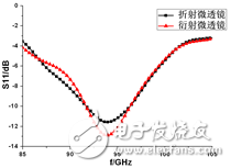
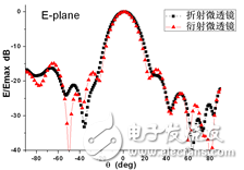
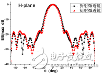
The S11 parameters and the E-plane and H-plane directions obtained by the refracting and diffractive microlens antenna CST simulation are shown in Fig. 3. As can be seen from the figure, the diffraction performance of the diffractive microlens is close to that of the refractive microlens. Considering that the diffractive microlens consists of only two cylinders, it is easy to process. Therefore, we can replace the conventional refractive microlens with a diffractive microlens.
(a)
(b)
(c)
Figure 3 microlens antenna S11 and pattern
0.1-6.2GHz Frequency Synthesizer
Synthesizer Price,Htcc Frequency Synthesizer,High Reliability Synthesizer,Small Size Frequency Synthesizer
Chengdu Zysen Technology Co., Ltd. , https://www.zysenmw.com