Our hands have had an electrostatic discharge (ESD) experience, and even if you just walk past the carpet and touch some metal parts, it will instantly release the accumulated static electricity. Many of us have complained about the use of conductive blankets, ESD electrostatic wristbands and other requirements in the laboratory to meet industrial ESD standards. Many of us have used expensive unprotected circuits to damage expensive electronic components.
ESD is a challenge for some people because it does not require any damage when handling and assembling unprotected electronic components. This is a circuit design challenge because it is necessary to ensure that the system withstands the impact of ESD and then still works properly. It is better that no user-perceived faults occur after an ESD event.
Contrary to common sense, designers can completely prevent a system from failing after an ESD event and still continue to operate. Keep this in mind, let's take a closer look at what's going on in the ESD shock, and then show you how to design the right system architecture to handle ESD.
Simple model
Charge a capacitor to a high voltage (typically 2kV to 8kV) and then release the charge through a closed switch into a "damaged" device ready to withstand ESD strikes (Figure 1). The polarity of the charge can be positive or negative, so both positive and negative ESD must be handled simultaneously.
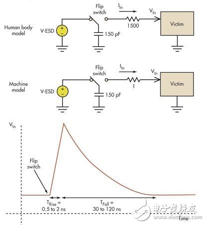
Figure 1: Board-level ESD typically involves machine models (MM) and human body models (HBM).
The high transient voltage that damages a damaged circuit typically has a rise time of a few nanoseconds and a circuit with a discharge time of about 100 nanoseconds. The sensitivity to positive and negative shocks can vary greatly, so you need to deal with them simultaneously. Good positive and negative impact. The difference between the two most common models of human body model (HMB) and machine model (MM) is mainly in series resistance. The conductivity of the mannequin is not as good as that of metal.
The best protection against overvoltage damage is to limit or clamp with a non-linear circuit (Figure 2). The most common are specialized diodes that have very low impedance when they are forward biased or in the Zener breakdown region. The introduction of a voltage limiter can quickly cause some other event because a large surge current flows through the voltage limiter through the capacitor discharge.
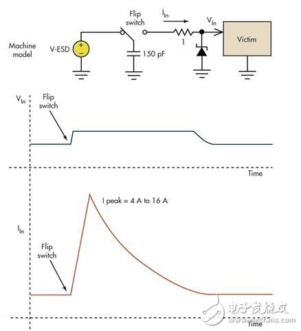
Figure 2: Basic voltage limiting circuit prevents overvoltage damage
Although high transient voltages are eliminated, replacing them with a few amps of inrush current can cause other problems in the system. Depending on the total impedance of the subsequent path, the inrush current can reach several amps. When designing I/O cells for a chip, it is common to see 4A to 16A of inrush current entering the device. Dealing with such huge transient surge currents has become a big problem in ESD design. Limiting the voltage is fairly easy, but the resulting current can reverse the circuitry and ground elsewhere in the system.
The current forced into the ground by the voltage limiter will cause an inductive ringing in that node of the system (Figure 3). The power supply typically travels along the ground and is a function of the power supply decoupling capacitance, so the system core still functions. However, the control lines connected to the board may be confusing because they are built relative to the ground outside the board. As a result, an ESD event can occur at a location and cause an input on the board to appear to be faulty.
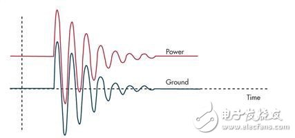
Figure 3: Injecting a large inrush current into the ground through a voltage limiter will cause a rebound in the PCB ground and behave as a function of the connected inductance.
We offer rechargeable li ion and Lipo Battery cells from industry's leading manufacturers, Panasonic cells, Sanyo cells, Moli cell, ATL cells, BAK cells, DLG cells, HYB cells, Samsung cells, LG cells, Maxell Cells. With contacts inside big manufacturers, we are able to supply authentic cells in wide variations of sizes, capacities, and power performances to meet your needs. In addtion we provide processing service to add proteced PCB in cell, to put heat shrink tubes, wires with designated connector, or to design unique plastic case with coaxial DC port.

Rechargeable Batteries,Rechargeable Lithium Batteries,Rechargeable Cell,Lithium Ion Rechargeable Batteries
Asarke Industry Co., Limited , https://www.asarke-industry.com