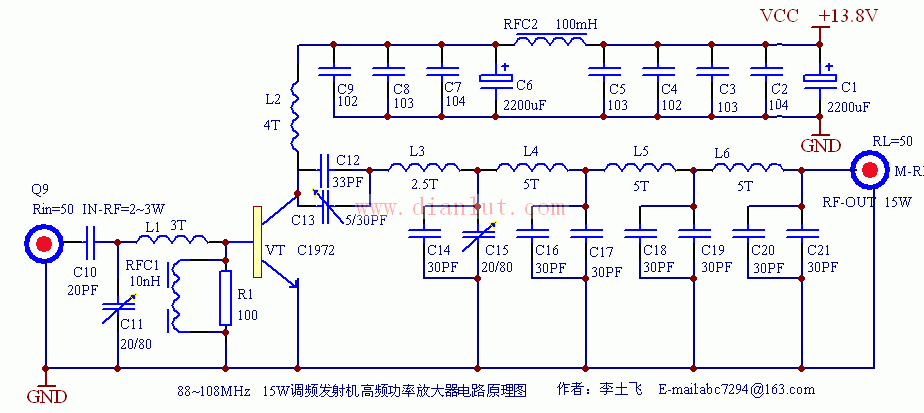
The power amplifier can extend the power of power 1-2W, 88-108MHZ FM transmitter to 10-15W. It is composed of single-tube type-C amplifier and multi-stage low-pass filter. It has high conversion efficiency and strong achievements. Wave suppression ability.
The circuit is shown in the drawing, using high-power transmitting tube C1972, its parameters are as follows: 175MHZ, 4A, 25W, power gain ≥8.5db, according to the parameters shown in the figure, the circuit working center frequency is about 98MHZ, input RF power about 2W , The rated output can reach 15W. In order to ensure that the output reaches the rated value at any frequency within 88 ~ 108MHZ, some components can be adjusted appropriately according to the center frequency of the previous stage. If necessary, the number of low-pass wave stages can be reduced to increase the output power. The expanded power signal is filtered by the three-stage low-pass filter to remove the higher-order spur components and fed into the transmitting antenna.
Component selection: In addition to electrolytic capacitors, other high-frequency ceramic capacitors are used, C11, C12, C14 use high-frequency characteristics, stable performance of adjustable capacitors, choke inductors RFC1, RFC2 finished inductors, must pay attention to RFC2 current For the carrying capacity, an inductor with a thicker wire diameter and a magnetic core should be selected. L1-L6 can be made of ø0.8mm high-strength enameled wire, with a diameter of about 5MM. The number of turns is indicated by the unit "T". Q1 uses ordinary Q9 sockets, which are used with plugs. Q2 uses a dedicated 50Ω RF output connector, the connection resistance is smaller, which is more conducive to impedance matching. The power amplifier tube uses the more common launch dedicated tube C1972. Of course, if you have enough silver and buy a high gain tube such as C2538, the power will be greater.
When debugging the circuit, you must pay attention to the fact that due to the high power of the circuit, you must connect a dummy load (I use 30 1W, 1500Ω high-precision metal film resistors made in parallel), and there must be sufficient heat dissipation devices, and the Power Supply during normal operation is not Less than 2.5A, the antenna impedance is strictly equal to 50Ω, short rod rod antenna can not be used, otherwise the strong RF feedback current will cause the circuit to interfere with itself, most of the RF energy cannot be radiated into the space and is consumed on the power tube, causing overheating damage ; Must be led to the outdoor antenna for transmission through a 50Ω coaxial coaxial Cable for transmission. The key to the normal operation of the circuit lies in the debugging of the circuit, and the whole process must be very careful. When debugging, only input a small excitation power, the power supply voltage drops to 9V, use a high-frequency voltmeter (can not use a general multimeter) to monitor the high-frequency voltage value at both ends of the dummy load, adjust C12, C14, L3, L4, L5, L6 1. Make the voltage amplitude reach about 15-20V, and then adjust C11 and L1 to make the voltage maximum. Then gradually increase the voltage. Each time the voltage is increased, C12, C14, C11, and L1 are adjusted repeatedly to make the output voltage the highest. Note that the voltage should be increased synchronously with the RF input excitation power to ensure the accuracy of the debugging results. When the rated value is reached, the working current is about 2A at a power supply voltage of 13.8V, the voltage at both ends of the 50Ω pure resistance dummy load is ≥40V, and the RF output power reaches 15W.
Using this RF power amplifier with a 50Ω umbrella-shaped omnidirectional vertical transmitting antenna (gain of about 2dB), tested with a common FM radio, the transmission distance coverage is not less than 15K.
This kind of power supply is also called industrial switching mode power supplies (SMPS) – It is a type of AC to DC, it obtains energy from the power grid, a DC high voltage is obtained through high voltage rectifier filtering, DC/DC converter obtains one or more stable DC voltage at the output end, and the power can be produced from several watts to several kilowatts for different occasions. The specifications of Switching Power Supply are various, the standard are 5V 12V 24V LED Power Supply, including single output, dual output and triple output power supply. They are widely used for LED strip, led module, led lamp and CCTV camera.
Power Supply
Power Supply,Switching Power Supply,Switch Mode Power Supply,12V DC Power Supply
Shenzhen Yidashun Technology Co., Ltd. , https://www.ydsadapter.com