Computer interface allows the 19th century organ to play on its own
How a group of engineers in Edinburgh, Scotland used the Xilinx Spartan-3E starter kit to create a robotic organist
Like many novel creations, it all started with a conversation in the bar.
"Do you know the pipe organ in the forest cafe upstairs?"
"know."
"We should create a robotic organist to play it."
"Of course, we should do this!"
A casual conversation prompted us to start the "WaldflOte Project".
My daily job is as the design manager of the IP department of Xilinx Scotland, but in my spare time, I am part of the informal organization "dorkbot", which aims to advance the grassroots between the engineering science and art world Collaboration; the activity slogan is "do bizarre things with electricity". I belong to the dorkbot in Edinburgh (may be called "dorkbot alba" or "dorkbot Edinburgh", depending on who you speak to). Our members have created many novelties, including pixel-mapped LED bowlers, automatic toothbrushes, illusion magic devices, electromagnetic screwdrivers, and various noise-generating boxes. There are very few accidental injuries.
The dorkbot Edinburgh team meets every Tuesday in the Forest Cafe, which is a non-profit meeting place run by volunteers, located near the University of Edinburgh. I attended a party held at this coffee house for a few weeks. One night, when I went upstairs to repair stage lighting, I was surprised to find myself in the church. There are preachers and choirs, the most important Yes, there is a 16-foot pipe organ.
In fact, the building where the coffee house used to be was the venue of the Congregational Church of Edinburgh-so there is an organ. But this is not the original home of this organ. At the end of the 19th century, the famous London organ manufacturers Gray and Davison first installed this organ in Dublin Castle, Ireland. In 1900, for some reason, this organ was transferred to Edinburgh. Since then, this organ has remained in Edinburgh after several repairs.
After chatting in the bar, we did not act immediately. In the following 7-month gathering, we kept thinking, exploring, and discussing, and finally designed several ways to manipulate the organ keyboard.
We named this project "Project WaldflOte" because a plug on the organ is called "WaldflOte". In German, it means "forest flute". Since the pipe organ is located in the Forest Cafe, it sounds poetic.
Use the correct mechanical parts
At the initial stage of development, we clearly divided the problem into two parts: mechanical and electronic. If we can find solutions to mechanical problems, we can build these two parts relatively independently.
One of the main factors restricting us is funds-we do n’t have much funds available, all of them are only funds raised by several of our core members. We traveled across the tailgate market and found some electromagnets at reasonable prices. We were able to get 100 such electromagnets at a unit price of about 1 pound (about 1.5 US dollars), and we ordered 6 to test on the pipe organ.
We found that the size of the electromagnet is very ideal, but the movement distance of the electromagnet core is slightly shorter than the movement distance required to consistently touch the white keys of the pipe organ. Although we can directly use the electromagnet core to drive the black keys, we still need some kind of lever to drive the white keys.
The first prototype of the electromagnet assembly is shown in Figure 1, which is a working principle diagram of the electromagnet. For the white keys, the back of the top plywood lever is hinged with pipe tape. When the electromagnet is energized, it will be pulled down. When the electromagnet is de-energized, the pipe organ itself provides upward force-so no additional spring is needed. For black keys, a small pin extending from the bottom of the electromagnet can press the key directly to play the note.
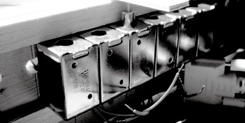
Figure 1: Prototype of electromagnet assembly.
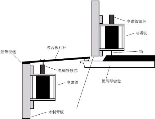
Figure 2: Mechanical layout.
Component testing has shown that the keys can indeed be successfully pressed. At the same time, it also shows that I can't divide the space where the electromagnet is placed into seven equal parts, and the interval cannot be close to the actual interval of the keyboard octave, so we can only test one key at a time. But we confirmed that this principle is feasible, so we continued our development work, ordered the parts suitable for the entire keyboard, and then proceeded to electronic design.
Electronic design
During the electronic design, we all sat down and roughly designed the electronic structure; Figure 3 is the basic structure diagram. On the left side of the figure, MIDI messages are passed in from outside (I will introduce the MIDI protocol in detail below). The right side of the figure is a shift register chain; the controller is responsible for switching the "clock" signal when driving the corresponding "data" value to fill the shift register chain, and then sends the contents of the shift register chain to the electromagnetic through the "strobe" signal in parallel The input of the iron driver.
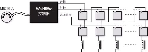
Figure 3: Electronic structure.
We have used the 74HC595 shift register IC in the shift register / driver chain. However, the electromagnet test shows that each electromagnet needs about 15V power to provide 350mA drive current-beyond the scope of the CMOS output stage. To meet this requirement, we added a ULN2803A Darlington output stage to each shift register IC. This chip also has a protection diode to shunt the high flyback voltage generated by the electromagnet when the current is cut off to avoid adding a discrete diode. We made several prototypes of driver circuit boards on the universal board, each of which can drive 16 electromagnets.
Controller design
Although we can take a variety of methods to design the controller (including using the Arduino platform or using other microcontrollers), we ultimately chose to use the Xilinx Spartan-3E starter kit because I used it in the daily work of Xilinx This kind of development board is familiar with related tools. In particular, I know how to use debugging tools such as Platform Studio SDK and ChipScope. Since this may be a field debugging project, it can save time. We use the Xilinx Embedded Development Kit to develop the core component MicroBlaze subsystem (Figure 4).
Figure 4: MicroBlaze subsystem.
In addition to the MIDI interface and the shift register interface, we also chose to add a serial RS-232 control port to help us debug the system. The RS-232 protocol looks a bit old-fashioned, but in such projects, its value is extraordinary. We have also added some GPIO ports for driving LEDs, reading switches and buttons to complete certain interactive operations without using the control port.
Write MicroBlaze firmware
We have determined that the best input interface for the system is the MIDI port. Since the 1980s, the Musical Instrument Digital Interface (MIDI) has become the standard interface for connecting digital instruments such as synthesizers to other musical instruments or control computers, so obviously we should also use this interface. MIDI will allow us to achieve maximum flexibility in organ connection.
MicroBlaze can internally display the status of the entire keyboard and which keys the system is pressing-that is, which electromagnets the system is powering up.
MIDI is a one-way low-speed serial protocol with a transmission rate of 31250 baud. It contains multiple types of information, but for our purposes, only NOTE ON and NOTE OFF are important types of information. Each NOTE ON message consists of 3 bytes.
The first byte is 0x9n, where n represents the number of channels.
The second byte is the number of notes from 0 to 127, and the middle C is the 60th.
The third byte is a speed value from 0 to 127.
NOTE OFF is very similar to this except that the first byte is 0x8n.
In our design, we decided to listen to all channels simultaneously ("omni" operation). Since the organ keyboard is not sensitive to speed, we can safely ignore all speed bytes.
The EDK UART IP core receives MIDI messages, and then sends one message to the MicroBlaze processor at a time through the FIFO. MicroBlaze can internally display the status of the entire keyboard and which keys the system is pressing (ie which electromagnets the system is powering up). The firmware uses a static look-up table to indicate the electromagnet associated with this note, which will be used as the index of the internal map; the arriving NOTE ON message sets the corresponding entry value to "1", and the NOTE OFF message sets the entry value to " 0 ".
After the internal map is updated, use the entire contents of the map to update the electromagnet register; through the bit splitting of the GPIO port, the MicroBlaze processor writes the contents of the map one bit at a time to the data input of the shift register, and then switches the clock signal to move the shift register. Once the entire shift register is updated with the content of the figure, MicroBlaze will write a rising edge to the STROBE line, which can copy the value of the shift register to the output register, power on or power off the correct solenoid, thus producing a pleasant music.
We use firmware as a software state machine; for embedded applications that do not use a real-time operating system, this can provide certain multi-threaded application functions, but without the actual thread implementation overhead. Based on the current state, the static structure array indicates what measures the system should take for a specific event.
const midi_state_table_entry_t MIDI_STATE_TABLE [] =
{
{INHIBITED, PANIC,
MidiSM_Panic, INHIBITED},
{ANY_STATE, PANIC,
MidiSM_Panic, INIT},
{ANY_STATE, INHIBIT,
MidiSM_DoNothing, INHIBITED},
{ANY_STATE, OTHER_STATUS_RECEIVED
, MidiSM_ClearMessage, INIT},
{INIT, NOTE_ON_OR_OFF_RECEIVED,
MidiSM_StoreStatusByte, NOTE_
ON_OR_OFF},
{INIT, DATA_RECEIVED,
MidiSM_DoNothing, INIT},
{NOTE_ON_OR_OFF, NOTE_ON_
OR_OFF_RECEIVED, MidiSM_
We successfully played some very complex, fast-paced music, from classical to rock; electromagnets and drives did not show much limitation in terms of speed.
StoreStatusByte, NOTE_ON_OR_OFF},
{NOTE_ON_OR_OFF, DATA_RECEIVED,
MidiSM_StoreNoteNumber, NOTE_ON_OR
_OFF_NUMBER},
{NOTE_ON_OR_OFF_NUMBER,
NOTE_ON_OR_OFF_RECEIVED, MidiSM_St
oreStatusByte, NOTE_ON_OR_OFF},
{NOTE_ON_OR_OFF_NUMBER,
DATA_RECEIVED, MidiSM
_NoteOnOrOffComplete,
NOTE_ON_OR_OFF},
{INHIBITED, ENABLE,
MidiSM_DoNothing, INIT},
{LAST_STATE, LAST_EVENT, 0,
LAST_STATE},
};
The first entry in the structure indicates the current state; the second entry indicates the arrival of the event; the third entry indicates that the state transition function is required to process the event; the fourth entry indicates the next state.
The codes used by the state machine business end are as follows:
XStatus MidiSM_
DoStateTransiTIon
(midi_state_machine_t * pInstance,
u8 event)
{
const midi_state_table_
entry_t * pTable = pInstance-
> pStateTable;
// Search for a match in the
state table
do {
if ((event == pTable-
> received_event)
&& ((pInstance-
> current_state == pTable-
> state)
|| (pTable-> state ==
ANY_STATE)))
{
(* pTable-
> transiTIon_funcTIon) ((v
oid *) pInstance);
pInstance-> current_state
= pTable-> next_state;
return XST_
SUCCESS;
}
pTable ++;
} while (pTable-> state! =
LAST_STATE);
// Aaargh, something bad happened-should never get here
XASSERT_NONVOID_ALWAYS ();
}
The event provided by the event loop is an argument for this function. Based on the current state and event, some measures are taken and the state of the system is changed. Types of events include bytes reaching the MIDI interface, characters reaching the control port, and pressing the panic button. All experienced MIDI players know that the restart button is an essential feature for ear protection and power supply-it can unconditionally turn off all solenoids and restore the system to a known safe state.
Playing WaldflOe
With this sophisticated controller installed, the robotic organist can play all styles of music from Rhapsody to Rock. Hidden at the bottom of the key is the wooden back plate of the electromagnet-30 or more electromagnets are installed on each plate, and some recycled tank capacitors are also installed to provide electricity for the electromagnet. We connected the entire driver assembly to the pipe organ. At the top of the figure, you can see the Spartan-3E Starter Kit development board and the interface universal board on the right side; we use recycled CAT5 cables to connect these devices to the drive components.
It is difficult to explain the operation of the pipe organ in words, so I suggest you click on the Internet link at the end of this article to watch the video we uploaded. When the robot organist plays "Moonlight Sonata" or "Jump", you will hear the click of the electromagnet-this is the sound of the electromagnet core when it falls to the bottom of the coil, not the lever hitting the key sound. However, if you sit in the hall instead of standing on the pulpit, the sound of the electromagnet will be much smaller. All you can hear is the beautiful music flowing from the organ.
We used this system to successfully play some very complex, fast-paced music, from classical to rock; electromagnets and drives did not show much limitation in terms of speed. Even when playing the most demanding tracks, the electromagnet power supply usually does not exceed 4A at 15V. Even if we overuse the electromagnet a little, the electromagnet coil does not show a significant temperature increase. All in all, we are very satisfied with this system, and we are very proud to participate in the development of this system.
What's next for WaldflOe? Oh, we have informally invited some musicians to create tracks for this new instrument (especially composers who are interested in 53-finger, never tired players), and we are also considering holding a recital. Another possibility is to realize the mechanization of the operation of the pipe organ plug, which is convenient for us to change the volume and timbre during the electronic performance. We are also considering adopting certain methods to drive the bass pedal of the pipe organ to make the longest bass pipe sound. Last but not least, we are planning to launch a service on the Internet to enable the public to upload their MIDI files to this system, and then listen to the live performance of the organ.
Kitchen series are linear actuators that can be used in kitchenware to make it smart. With actuators, extractor hood can be hide, working cabinet can be adjustable to the suitable height, and wall cabinet can be up and down, etc. Some are tiny enough for limited space, some are long and strong enough (15,000N) for big load.
Kitchen Actuator,Kitchen Ventilator Actuator,Kitchen Linear Actuator,12V Kitchen Actuator
TOMUU (DONGGUAN) ACTUATOR TECHNOLOGY CO., LTD. , http://www.tomuu.com