In people's daily work or life, applications such as laptops or desktop computers are not always full or heavy-duty, but are in standby or light-load mode for a significant amount of time. In today's consumer awareness of energy conservation and increasingly stringent energy efficiency regulations, the light load or standby energy performance of power supplies is increasingly valued by heavy designers. This article introduces the main features of the ON Semiconductor NCP1937 power management combination controller, helping designers design energy-efficient, low-standby (<10 mW) power supplies of more than 75 W, suitable for all-in-one and notebook adapters and LED TV power supplies. .
Introduction to the basic features of NCP1937
The NCP1937 is a new Combo Controller from ON Semiconductor that integrates a power factor correction (PFC) controller and a quasi-resonant (QR) flyback controller in a single chip for compact, high design Power supplies such as energy-efficient, standby, and light-duty adapters with very low energy consumption.
The NCP1937 has features such as Power Save Mode (PSM) that reduces standby power consumption to less than 10 mW. The controller includes a high voltage start-up and active input filtered X-capacitor discharge circuit to help reduce external component count and reduce standby power consumption. Its integrated quasi-resonant controller with valley lock provides noise-free operation. The NCP1937 integrates a high voltage input undervoltage detector and also integrates a high voltage switch to disconnect the PFC feedback resistor divider to reduce standby power consumption. The NCP1937 supports a wide VCC range of 9 V to 30 V with built-in overvoltage protection. It also contains a 0.5 A/0.8 A source/æ±² current gate driver.
The NCP1937 is available in a SOIC-20 package. Figure 1 shows its pin configuration. Among them, the HV/X2 pin is used for the high-voltage startup circuit input, and is also used for input X capacitor discharge. The BO/X2 pin performs an input undervoltage detection for the entire IC and is also used to discharge the input X capacitor and detect the line voltage range. PControl controls the PFC conduction error amplifier output, and the compensation network connects this pin to ground to set the loop bandwidth. The resistor connected between the PONOFF pin and ground sets the PFC off threshold. The PSTImer pin performs power saving mode control and timer adjustment. See the NCP1937 data sheet for more pin functions.
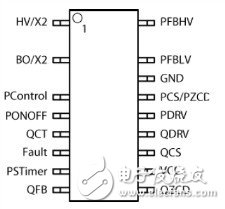
Figure 1: NCP1937 pin configuration diagram.
Detailed explanation of key functions of NCP1937
The NCP1937 combo controller integrates a PFC controller and a QR flyback controller. Among them, the PFC controller operates in critical conduction mode (CrM) with valley switch, constant on-time control and maximum frequency clamp function. In some applications it is required to turn off the PFC converter when the load is light to optimize system energy efficiency. The PFC controller in the NCP1937 uses a novel architecture to determine the output power and enable/disable the PFC segment based on the output power. For example, the user can adjust the PFC segment shutdown threshold and provide different PFC segment shutdown threshold levels for AC voltages in the US and Europe, which can reduce the output bulk capacitance. The PFC controller's follow-up boost architecture independently adjusts the PFC output voltage based on the AC line voltage (250 V for AC voltage input in the US and 400 V for AC/ES AC input conditions) and reduces power dissipation. Line voltage feedforward adds dynamic range and increases noise immunity. The PFC controller also provides excellent transient load response as it includes a Dynamic Response Enhancer (DRE). The soft overvoltage protection feature reduces the likelihood of audible noise during load transients. Other features include: forward current sensing, combined with PFC zero current detection (ZCD); 250 kHz frequency clamping and light duty duty cycle operation; rich safety features such as fast overvoltage protection (OVP), PFB pin Open circuit protection, boost and bypass diode short circuit detection.
The flyback controller operates in a quasi-resonant peak current mode with a valley lock function. The quasi-resonant flyback controller switch driver (QDRV) is delayed by 3 μs during shutdown, blanking the leakage current ringing effect. The flyback controller has a built-in 4 ms soft start and includes a 128 ms timer for short-circuit detection (providing automatic recovery or latch selection). The flyback controller supports a light-load mode of operation with a voltage-controlled oscillator (VCO) operating mode after the fourth valley, with the lowest frequency limited to 23.5 kHz; forced to enter the skip-cycle mode when the load is lighter, further saving energy ( See Figure 2). Other features include combined power compensation on the ZCD pin.
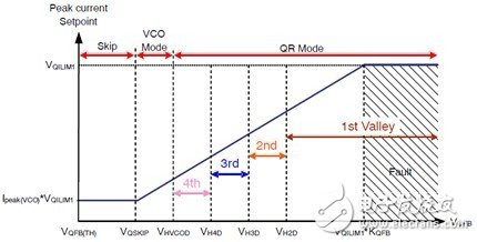
Figure 2: The operating valley of the QR flyback controller in NCP1937 at different feedback input voltages.
Performance Test of 85 W Adapter Demonstration Board Based on NCP1937
ON Semiconductor has developed an 85 W adapter demo board based on the NCP1937 combo controller (see Figure 3). The demo board operates over a wide range of input voltages and provides a nominal output voltage of 20 V. In addition to the NCP1937, the demo board uses the ON Semiconductor NCP4303 secondary-side synchronous rectification controller to provide secondary-side synchronous rectification and uses the NCP4355 secondary-side controller from ON Semiconductor for low standby power adapters for secondary side No-load detection control.
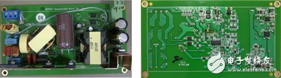
Figure 3: 85 W Low Standby Power Adapter Demo Board based on NCP1937, NCP4303, and NCP4355.
Figure 4 shows the energy efficiency test data and graphs of this demo board under different output power conditions. Tests show that the 85 W demo board has an energy efficiency of 91.28% at 115 Vac and 92.99 W input power (Pin). At 230 Vac and 91.85 W Pin, the energy efficiency is 92.41%; the average energy efficiency is as high as 90.18%.
This demonstration board provides very low energy consumption under light load conditions and also provides high energy efficiency. For example, under 115 Vac and 5.027 W Pin, the energy efficiency is 79.85%; while at 115 Vac and 11.640 W Pin, the energy efficiency is 85.91%. At 230 Vac and 5.055 W Pin, the energy efficiency is 79.13%; at 230 Vac and 11.869 W Pin, the energy efficiency is 84.25%.
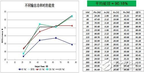
Figure 4: The NCP1937-based 85 W adapter demo board delivers an average energy efficiency of up to 90.18%.
As mentioned earlier, the NCP1937 includes a unique power-saving mode (PSM) that can be used to minimize the standby power consumption of the adapter under no-load conditions. PSM operation is controlled using external control signals. In fact, the secondary side controller NCP4355 senses the output load of the Power Supply (VOFFDET). When a light load condition is detected, the controller will send a signal through the optocoupler to instruct the NCP1937 to enter the power save mode. The command signal forces the controller to perform a power save mode (PSM) by pulling the PSTImer pin above the 3.5 V threshold. At PSM, VCC will be able to discharge until it reaches the regulation point. In fact, the NCP1937 alternately turns on the HV/X2 and BO/X2 startup circuits every half cycle, and regulates VCC to VCC (PS_on), typically 11 V. The data measured when the 85 W demo board is connected with a two-wire connection shows that the NCP1937 consumes only 4.82 mW in power-saving mode at 115 Vac and 8.68 mW in power-saving mode at 265 Vac.
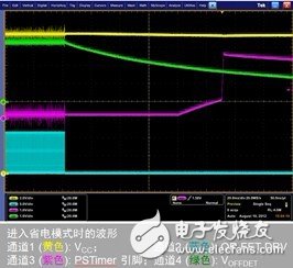
Figure 5: Waveform into Power Save Mode (PSM)
It is worth mentioning that in order to comply with the safety regulations, the AC-DC power supply must automatically discharge the EMI input filter X2 capacitor within less than 1 second after the plug is dialed from the AC outlet. To meet this requirement, a string of high impedance resistors is typically used in parallel with the capacitor. But this resistor chain consumes about 25 mW of input power, which is particularly dazzling under no-load conditions. In order to effectively discharge the X2 capacitor while reducing the no-load energy consumption, ON Semiconductor's solution is to detect the AC connection condition and discharge the capacitor through an internal switch, saving no-load energy consumption. The steps for the NCP1937 to discharge the X2 capacitor are:
1) When the AC voltage is removed (out of the AC plug), the voltage on the BOX2 and HVX2 pins becomes static. The rated 95 ms timer must be used up to allow the control IC to notify that the AC voltage has been removed. The drive pulse stops when the communication line is removed.
2) The Vcc voltage is discharged from the internal pull-down current source (rated current 11.5 mA) to the Vcc(off) threshold.
3) Once Vcc is pulled down to Vcc(off), the startup current source is turned on at a nominal 3.75 mA current and the charge stored in the X2 capacitor is transferred to the Vcc capacitor.
Depending on the relative size of the VCC capacitor and the X2 capacitor, it is possible to bring the Vcc voltage to the Vcc(on) threshold and restart the controller. The AC line must then be detected again.
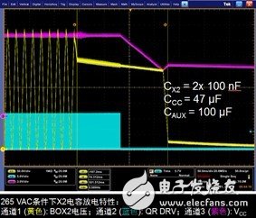
Figure 6: NCP1937 discharges X2 capacitors by detecting AC conditions, saving no-load energy
The NCP1937 also provides excellent power factor at higher load conditions. Tests show that the 85 W demo board has power factors of 0.978, 0.984, and 0.985 at 50%, 75%, and 100% load at 115 Vac, respectively; power factor at 75% and 100% load at 230 Vac, respectively Up to 0.943 and 0.956.
summary:
ON Semiconductor's NCP1937 combo controller integrates a PFC controller and a quasi-resonant flyback controller. It is an energy efficient, low standby power (less than 10 mW) solution for power applications up to 75 W. Such as notebook and desktop all-in-one power adapter. This article introduces the key features of the NCP1937 and the energy efficiency test results of the 85 W power adapter demonstration board based on NCP1937. It explains how some key functions work, helping designers better understand the characteristics and advantages of this combination controller to develop energy efficiency. , 75 W or more power supply scheme with low standby energy consumption.
The material of this product is PC+ABS. All condition of our product is 100% brand new. OEM and ODM are avaliable of our products for your need. We also can produce the goods according to your specific requirement.
Our products built with input/output overvoltage protection, input/output overcurrent protection, over temperature protection, over power protection and short circuit protection. You can send more details of this product, so that we can offer best service to you!
Speaker Adapter,Portable Speaker Adapter,Durable Speaker Adapter,Mini Speaker Adapter
Shenzhen Waweis Technology Co., Ltd. , https://www.waweis.com