I know that I am fascinated by everything related to electronics, but no matter from what angle, today's field programmable gate arrays (FPGAs) seem to stand out from the crowd. They are really great devices. If in this intelligent age, in this field, you want to have a skill, you have not paid attention to FPGA, then the world will abandon you, the era will abandon you. The author of this public account, ALIFPGA, has many years of experience in FPGA development. All articles are a summary of years of study and work experience.
Digital filters are often used to modify or change the characteristics of signals in the time or frequency domain. The most common digital filter is a linear time-invariant LTI filter.
The finite impulse response FIR filter is an LTI filter. The relationship between the output of the N-th order FIR filter and the input time series xn is as follows:
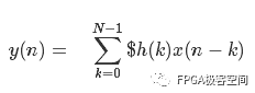
hk is the filter coefficient.
y0 = h0 * x0
y1 = h0 * x1 + h1 * x0
y2 = h0 * x2 + h1 * x1 + h2 * x0
.................................................
The formula expands as above, and the FIR filter can be implemented using the distributed algorithm introduced earlier.
FIR filters have multiple implementation forms:
Equal ripple
Least Squares
Window function, etc.
Equal ripple design method:
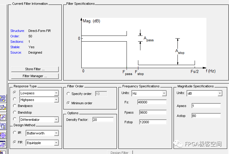
As shown in the figure above, FIR and other ripple low-pass filter filters, the parameter design under matlab, through the fadtool of matlab, the coefficients of the filter can be obtained, thereby achieving the final FIR filter design.
Response Type: Select the type of FIR filter: low pass, high pass, band pass, band stop, etc. In the DDC / DUC module design, the extraction and interpolation need to use the Halfband Lowpass type, and the channel filter needs to use the Raised-cosine type.
Design Method: There are many FIR filter design methods, the most commonly used are Window Function Design (Window), Equiripple Design (Equiripple) and Least Squares (Least-Squares). Among them, the window function design method is mainly explained in the school classroom. It is mentioned that the FIR filter will definitely think of hamming and kaiser windows, but it is rarely used in practical applications because if the window function design method is adopted, the desired frequency response is achieved Compared with other methods, there are often more orders; and the window function design method generally only refers to the pass band wp, the suppression band ws and the ideal gain to design the filter, but the ripple of the pass band and the suppression band in practical applications also needs to be considered Yes, in this case, the equal ripple design method is very suitable.
Filter Order: Set the order of the filter. This option directly affects the performance of the filter. The higher the order, the better the performance, but the corresponding resources required for FPGA implementation will increase. There are 2 options in this setting: Specify order and Minimum order. Specify order is the order of the engineer to determine the filter. Minimum order is to let the tool automatically determine the minimum order required to reach the desired frequency, so which one to choose The options depend on the actual situation.
density factor: This parameter controls the density of the frequency network. Increasing the value of this parameter can make the designed filter closer to the ideal frequency response, but this will increase the amount of filtering calculation. Because filter design requires that each frequency point on the frequency network must meet the specifications of the ideal filter, the denser the frequency network, the more complex the filter formula designed.
Frequency Specification: Set the parameters of frequency response, including sampling frequency Fs, passband frequency Fpass and stopband frequency Fstop.
magnitude specifications: Define the magnitude attenuation, the unit is db, decibel. Apass means passband attenuation, Astop means stopband attenuation. Apass / Astop = 20 * log10 (output / input).
The filter designed by the equal ripple best approximation method has the same ripple characteristics of the pass band and the stop band, and the maximum attenuation of the pass band and the minimum attenuation of the stop band can be controlled separately, so the indicators are evenly distributed and there is no waste of resources, so the order The number is much lower.
The Description of 2G/3G/GSM/4G/5G Antenna
Frequency of 5G Antenna: 885-900mhz/1800-2170mhz
2G/3G/GSM/4G/5G Antenna is mainly used for communication, which can enhance the signal of mobile phone, computer and wireless Internet. 2G/3G/GSM/4G/5G Antenna has indoor and outdoor, Outdoor Antenna is waterproof, sun protection, lightning protection , Corrosion.
The Picture of the Description of 2G/3G/GSM/4G/5G Antenna:


2G Antenna,3G Antenna,GSM Antenna,4G Antenna,5G Antenna
Yetnorson Antenna Co., Ltd. , https://www.yetnorson.com