This paper proposes a design scheme of optometry control system based on FPGA and USB interface. The interface design of automatic computer optometry in this scheme is improved on the basis of the original refractometer, and an automatic computer control system based on FPGA is designed. And the use of advanced USB technology to connect devices and computers, increased data transmission rate, increased positioning accuracy, and shortened the time of the optometry process.
1 Introduction
In recent years, myopia has seriously affected people's health. In order to accurately understand the degree of myopia in the eyes of myopia patients, and to provide more suitable glasses for myopia, optometry equipment has become an indispensable equipment in the optical retail industry. At present, the mainstream computer refractometers on the market cannot fully realize the automation of the optometry process. The problems are mainly manifested in the following three aspects:
1 The positioning speed is slow; 2 the positioning accuracy is poor; 3 the automation level is low.
In order to solve the above problems, the design of the original computer refractometer has been improved, using a fast running speed, high stability FPGA control stepper motor drive chip, to achieve the three-axis linkage of the refractometer; the use of the stroke switch to achieve the pole Automatic round trip between. In order to protect the circuit safety, the photoelectric isolation circuit between the boards is designed; and the advanced USB technology is used to communicate the computer and the device, which increases the data transmission rate and improves the controllability of the device.
2. System hardware overall design
The control system is the control core of the refractometer. It not only realizes the movement and light source control of the multi-axis stepping motor, but also realizes the interaction with the information of the upper computer and other important functions. The design of the main control board of the refractometer is extended by the EP3C16Q240C8 minimum system. According to the FPGA function implementation and related peripheral extensions, the pin interface is appropriately changed, and the USB communication interface, stepping motor drive module and stroke switch signal input are added. The optical isolation circuit at the end. The block diagram of the hardware circuit design of the main control board of the optometry control system is shown in Figure 1.
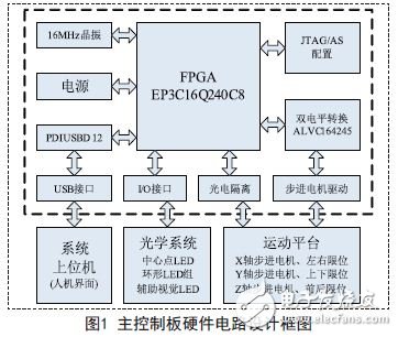
The FPGA in the main control board uses the Cylone III series chip EP3C16Q240C8N produced by Altera. The chip has 15,408 logic units; it can provide 516,096 bytes of RAM. In addition, the chip also has 4 phase-locked loops inside. It can guarantee the stability of the system clock signal when running at high speed. The stepper motor driver chip chose to use the SLA7042M, a two-phase stepper motor dedicated driver chip from Allergo, which enables ultra-smooth low-speed driving. In order to realize the communication between the main chip and the external device, the control board needs to convert the levels of 3.3V and 5V to each other. The system uses the 16-bit 3.3V-5V level conversion chip produced by TI Company SN74ALVC164245. The USB interface control chip adopts PDIUSBD12, which integrates The SIE FIFO memory, transceiver, and voltage regulation period are suitable for many external devices.
3.Verilog hardware function implementation
Verilog HDL is a hardware description language used for digital system modeling from algorithm level, gate level to switch level. The FPGA chip is the core component of the refractometer main control board. It is used in this design. Verilog HDL realizes the information interaction between the lower computer and the upper computer, the control of the multi-axis linkage stepping motor motion platform, and the control of the light source on the FPGA. The internal functional modules of the FPGA are shown in Figure 2.
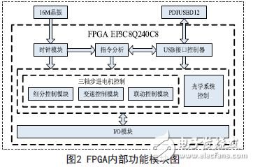
1) USB interface control module: FPGA internal USB firmware program, realize FPGA and host computer USB interface communication.
2) Clock module: divides and multiplies the external 16MHz clock to generate clock signals of various frequencies required for FPGA operation.
3) Instruction analysis module: analyzes the received upper computer command, generates an execution command according to the specified instruction protocol, and sends the execution instruction to each execution module.
4) Stepping motor control module: Execute the three-axis stepping motor control command delivered by FPGA, subdivide and shift control the motor of each axis, and finally realize the motor by sending different commands to the special driving chip of stepping motor. Axis linkage.
5) Light source control module: 5 LED infrared light sources and 3 visual auxiliary light sources for controlling the optical system. 3 visual auxiliary light sources guide the human eye gaze direction, and 5 LED infrared light source assist system focus function.
4. The implementation of the host computer application and driver
The computer software of the computer optometry control system is mainly responsible for the function of video image acquisition and processing. On the basis of preprocessing, a series of instructions such as morphological processing, target recognition and spot parameter calculation output are completed, and the instructions are passed through the USB interface. Transfer to the lower computer. Since the device is not a class device, it is necessary to write a special driver and software in order for the device to work properly.
4.1 Driver Writing
The driver is written using some specialized tools for driver development, such as Driver Studio, WinDriver, and so on.
Driver Studio 3.2 is developed. The development steps are not listed here. It should be noted that the information corresponding to the device description in the firmware is entered in the USB Vendor ID and USB Product ID. Since the Philips PDIUSBD12 chip is selected, the Vendor ID of the device is fixed at 0 or TImes; 0471.
After using Driver Studio's Driver Wizard to generate the driver framework, you can use Visual C++ 6.0 to modify the functions in the project file generated by the Driver Wizard, as well as the custom IO control interface functions and vendor requests. write. Once this is done, the driver can be compiled, and after successfully compiling the driver, it will be automatically generated by Driver Studio. The inf file is placed in the same directory, and it is fine to specify this directory when looking for the driver.
4.2 Writing of the host computer application
Since the device uses the USB interface to communicate with the device, the host application must access the device through the USB driver. The application for writing the host computer must conform to the interface specification defined by the USB driver. In general, after using the Driver Wizard to generate a driver project, it will also generate an ioctl.h file, which is the bridge between the application and the driver. It defines the driver interface when writing the application. Need to refer to it.
The upper computer application is divided into six areas, a video display area, a (direct control) operation area, a MOTOR control area, an LED control area, a real-time processing (data) display area, and a state feedback data display area.
The human-computer interaction function of this system is designed by using VC++6.0 compiler environment on windows platform. It can visually display the tracking focus process and perform simple control of visual human eye tracking control program. The human-machine interface can realize the human eye tracking system. fully control. The completed human-computer interaction interface (host computer application), the specific implementation code will not be described again.
5. System construction and testing
The automatic computer optometry control system is divided into two parts, the upper computer and the lower computer. The communication is connected through the USB bus to complete the whole system function. Through the VC6.0++ development environment programming to achieve the upper computer software of the windows platform, the device can be controlled through its human-computer interaction interface. The upper computer software realizes the control of the CCD camera in the head of the computer optometry instrument, the real-time collection and processing of the video data, the issuance of various control commands, and the display of data information.
The complete system test is carried out on the set working platform. The result is shown in Figure 3. The human-computer interaction interface can clearly and completely observe the images acquired after the tracking has been completed.
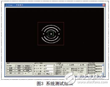
Through the analysis of the test results, the control system can complete the tracking task well, the identification is accurate, the tracking is fast, the focus is accurate, and the feasibility of the system is fully verified, which basically meets the design expectations.
6. Conclusion
This solution uses PC and FPGA to design a complete control system, which fully utilizes the characteristics of PC in image processing, human-computer interaction, FPGA hardware resources and reconfigurability, greatly improving The real-time processing capability of the system shortens the tracking time and improves the tracking efficiency. The system test shows that the computer optometry control system designed by this scheme will be an indispensable part of the whole refractometer system.
LED wall packs & wall pack lighting saves on operation cost compared to metal halide fixtures. Led Wall Pack is a compact and lightweight outdoor fixture designed for parking lots, walkways and doorway.Led Wall Lamp features a classic design, so you don't have to update your look by swithing to energy saving LED technology.Wall Pack Light Fixture is designed for outdoor wall mounted lightingapplications requiring white uniform light, long life and low maintenance.LED wall pack fixtures are with cutoff and full glass styles. LED wall pack lights are used for energy efficient commercial lighting,they will light up your business's outdoor area the way you want.

Led Wall Pack,Solar Wall Lights,Led Wall Lamp,Wall Pack Light Fixture
Shenzhen Bbier Lighting Co., Ltd , https://www.chinabbier.com