With the rapid development of computer and information technology, AGV smart cars have been widely used in transportation, warehousing and other industrial fields. Especially with the rapid development of modern logistics industry, the problem of transportation and storage cost has become a problem that logistics enterprises can't ignore in cost accounting. Realizing zero inventory of products is one of the goals of saving cost and improving product competitiveness. On the one hand, in order to save costs, to achieve zero inventory; on the other hand, in order to obtain scale benefits and expand the reserve warehouse, to achieve automatic return and automatic outbound of different products, a smart device that can realize automatic operation is needed. To complete these unmanned tasks, achieving the goal of efficient management and automatic control. The AGV smart car happens to be able to do this. Based on the principle of single-chip microcomputer, this paper discusses and simulates the working mode of automatic returning and automatic unloading of products in the warehouse of AGV smart car.
This article refers to the address: http://
1 program selection and hardware circuit design
1.1 MC9S12DJ128 MCU
The MC9S12DJ128 MCU is a 16-bit MCU whose internal components are mainly composed of the basic part of the MCU and the CAN function module. The basic parts of the MCU mainly include:
(1) Clock and reset generation module CRG (Clock and Reset Generator). Includes low current or standard oscillator options, phase-locked loop clock frequency amplifiers, watchdogs, real-time interrupts, and clock monitors.
(2) Memory includes 128 KB of Flash, 8 KB of RAM, and 2 KB of EEPROM. With 5V input and drive capability, the CPU can operate up to 50 MHz and supports single-wire background debug mode (BDM) for online debugging.
(3) 29 independent digital I/O interfaces, 20 digital I/O interfaces with interrupt and wake-up functions; 2 8-channel 10-bit A/D converters with external transfer capability; 8 channels Input capture/output compares, with 8 programmable PWM channels, can be configured as 8-channel 8-bit or 4-channel 16-bit PWM, with each channel's period and duty cycle independently programmable.
(4) It has two serial asynchronous communication interfaces SCI, two synchronous serial peripheral interfaces SPI, Byteflight, Inter-IC bus and SAE J1850 Class B data communication network interface [1].
In order to realize the unmanned operation of the control of the AGV smart car, the design of the hardware circuit mainly includes the path information acquisition and separation module, the power management module, the steering gear control module, the motor drive control module and the speed detection control circuit. Its design block diagram is shown in Figure 1.
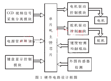
In order to facilitate hardware circuit debugging, facilitate the segmentation processing of hardware circuits, avoid signal interference and crosstalk problems that may occur in hardware circuits, and facilitate the design of mechanical structures, the design adopts modular design, and different modules can pass shielded wires or coaxial cables. Signal transmission is realized, and the effect is ideal through experiments.
1.2 Power Management Module
In this design, the AGV smart car is powered by a 7.2 V battery pack. The commonly used DC low voltage control circuit can adopt switching regulator and series voltage regulation. The switching regulator chip has high working efficiency but the circuit has large power supply noise, which is suitable for circuits with large power consumption [2]. When the battery voltage of the circuit becomes low due to consumption, the output voltage of the general-purpose LM7805 chip is difficult to guarantee, and it is easy to cause self-reset of the microcontroller. In addition, considering that the drive motor has a large current, especially when the smart car starts and accelerates, it may cause a relatively large output voltage drop of the battery.
Based on the above considerations, the main control chip of the design power module adopts MAX1771CSA and MAX1626ESA respectively. The chip has a large voltage input range, which can effectively ensure the large voltage of the voltage regulator circuit due to the loss of the output voltage of the battery. Fluctuation output. The MAX1771CSA is used to form a 12 V boost circuit, and the MAX1626ESA forms a 5 V step-down circuit. The main control circuit of the MCU, the servo drive and the speed detection all require a control voltage of +5 V, while the video acquisition circuit requires a +12 V control voltage. The power supply module is designed to meet the control requirements.
1.3 CCD video capture separation module
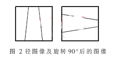
This article uses the Clarion CC-450 vehicle front-end camera, which is an NTSC system that scans 525 lines of 30 frames/s. The CCD camera outputs a standard video composite signal, which converts the image information into a one-dimensional video analog signal output by means of line scanning. By comparing the characteristics of the image resolution of the S12 MCU and the image resolution required for path detection, it can be found that when the CCD camera is installed, as long as it is rotated by 90°, the image information will also be rotated by 90°, as shown in Figure 2. Show. The image information acquired by the A/D converter, the horizontal resolution and the vertical resolution are interchanged, from the original image with low horizontal resolution and high vertical resolution to high horizontal resolution and low vertical resolution. The image can meet the requirements of road parameter detection.
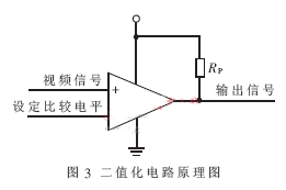
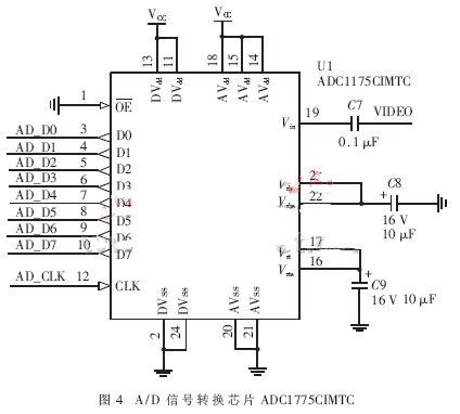
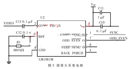
Due to the large amount of signal data collected by the camera, the A/D conversion I/O port that comes with the MCU itself may not meet the requirements. Therefore, another A/D signal conversion is used in this design. The chip ADC1775CIMTC is used to meet camera signal acquisition and conversion. The A/D conversion of the step signal separation chip LM1881 and ADC1775CIMTC can acquire the video signal, thereby obtaining the gray image data of the CCD, and the binarization process can obtain the dot matrix of the black path track on the image [3], the video The signal is compared with the set value by a comparator to obtain a binarization of the video voltage. The schematic diagram of the binarization circuit is shown in Figure 3. The A/D signal conversion chip ADC1775CIMTC is shown in Figure 4. Adjust the set voltage comparison value, and set the value to the boundary voltage value of black and white bright color in the video signal to improve the output image recognition effect. The camera acquisition circuit is shown in Figure 5.
1.4 Motor drive module
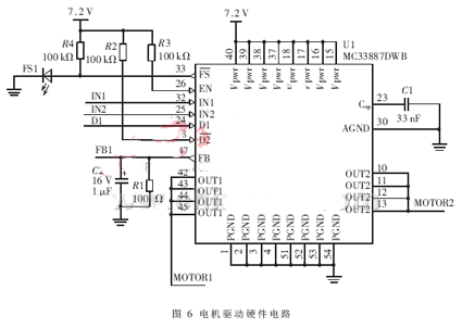
The RS-380SH type drive motor is used on the AGV smart car. In order to reliably ensure the speed of the smart car and improve its load capacity, this design uses two MC33887 chip drive motors with short circuit protection, under voltage protection and over temperature protection. To ensure the driving ability of the motor, to achieve speed control. By introducing various states into the interrupt port of the single chip microcomputer, the single chip microcomputer can process the abnormal situation of the outside world in real time. A two-part circuit is symmetrically arranged, as shown in FIG. 6 as one of the hardware circuits.
1.5 steering gear control module
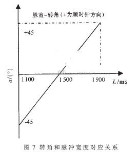
This design uses the SRM-102 steering gear with a response speed of 0.2s/60°. The pulse that controls the servo can be generated using the 1-way PWM of the S12 microcontroller. There are 8 PWM output ports in the MCU, which can cascade the adjacent 2 PWM outputs into a 16-bit PWM output. When the microcontroller is 24 MHz, set the cascade PWM period constant to 60 000, corresponding to the pulse signal with a PWM period of 20 ms. When the PWM duty constant is 4 500, the corresponding output is 1.5 ms. Changing the duty cycle constant can change the width of the output pulse. In addition, the linear relationship between the pulse width and the rotation angle is calculated as:
a=(L-1.5)×90°
Where a is the corner of the steering gear in degrees (°); L is the pulse width in ms.
The correspondence between the corner and the pulse width is shown in Fig. 7.
During the test, it was found that the certain angle of the steering gear had a time delay. The time delay was proportional to the angle of rotation and inversely proportional to the response speed of the steering gear. It can be seen from the analysis that the response speed of the steering gear directly affects the speed of the turning of the trolley. And at the actual control site, it also affects the accuracy of the steering. Through continuous testing, it is found that the height of the camera can be raised appropriately so that it can detect further distances, collect curve information in advance, and respond to the servos in advance. However, there is also a problem that if the camera is lifted too high, the gray value of the collected path will be low, and a suitable combination point must be found through continuous experimentation.
1.6 speed detection module
This design uses a cogging disk plus a direct-fire photoelectric photoelectric sensor to form a vehicle speed detecting circuit. The cogging disk rotation pulse is read by the photoelectric sensor. The voltage signal output by the sensor can be read by the A/D port of the MCU, and the remaining output pulse signals can be input into the timer/counter module of the MCU using the I/O port of the MCU for measurement. By periodically reading the count value of the counter, the frequency of the pulse can be reflected, thereby obtaining the vehicle speed information.
Let n be the rotation speed of the rear axle (unit: r/s); N is the number of pulses recorded by the photoelectric sensor in one sampling period T; P is the number of teeth of the cogging disk; T is the sampling period (unit s). then:
N=T×n×P (1)
Therefore, the speed of the rear wheel of the car is:
n=N/(P×T) (2)
After measuring, the diameter of the rear wheel of the trolley is D=55 mm, then the instantaneous speed of the trolley can be obtained as follows:
V=π×n×D (3)
The gullet disc fixed to the rear axle is a slotted disc whose circumference is divided into 60 equal parts. The speed sensor generates a pulse signal after one tooth and one notch on the cogging plate continuously pass through the speed sensor. After the shaping process, the I/O port of the single chip microcomputer is used for counting and capturing. Each time a pulse signal is captured, the distance traveled by the smart car can be obtained by the following formula:
L=1/60×π×D (4)
Substituting D=55 mm into equation (4) gives:
L=1/60×π×55 mm=2.879 mm (5)
It can be determined through testing that the best results are obtained when the speed sampling period is 0.2 s. If the sampling period is too long, the number of pulse accumulators is too large, which is detrimental to the algorithm during software programming. Based on the above analysis, the timer time is set to 48 ms, that is, every 48 ms, the timer generates an interrupt and reads the value in the pulse accumulator. Set the PID algorithm to change the motor drive signal after 4 intervals, and then change the speed of the smart car. The detected value (feedback value) in the PID algorithm is obtained by averaging the values ​​of the four read pulse accumulators, and the purpose thereof is to prevent the detection signal from abrupt and interfere with the control. In order to filter out the interference signal, a moving average filter is added to the PID control algorithm. After setting the timer set value and the pulse accumulator as described above, it can be inferred that the speed expression of the smart car is as shown in equation (6), thereby completing the measurement of the speed of the smart car.
V=(L×N)/48 (6)
1.7 keyboard display control module
The single-chip microcomputer used in this design has an I/O port that can be used to expand the keyboard and display. The hardware design directly uses an external 8-pin plug-in 4×4 keyboard, and an external dot matrix liquid crystal display module with a font library for convenience. Correct the path deviation of the smart car during operation during the debugging process. In the actual control site, the wireless communication module can be used to transmit commands to the AGV for remote control [1].
2 system software design
2.1 System initialization
At the beginning of the system operation, initialization is first required. The initialization mainly includes clock initialization, A/D port initialization, PWM initialization, IRQ initialization, and I/O port initialization. Among them, A/D and IRQ are used in the CCD image acquisition process, and PWM is mainly used in the control of the steering gear and the control of the motor drive.
2.2 PID algorithm design
The steering angle and motor speed algorithm starts from the farthest line of image and determines whether the line is valid according to the preset flag. If it is not a valid line, the next line is judged until a valid first action is found. Find the valid line to get the position information of the center line, continue to find the last line of valid black lines, and calculate the slope of the black line accordingly. The center position of the black line and the slope of the black line are substituted into the steering gear control amount and the center position formula of the design, and the control amount of the steering gear is calculated to determine the corresponding steering angle and the motor speed. Calculated as follows:
Steering gear control amount = proportional control amount + integral control amount + differential vacancy (7)
In the formula, the proportional control amount is obtained by multiplying the center position of the black line by the proportional coefficient, the integral control amount is calculated according to the slope of the black line, and the differential vacancy amount is the difference between the K-th and K-1th proportional control amounts [5] . The coefficient values ​​of each control amount are selected by testing.
For the control of the motor speed, it is mainly determined whether the smart car is driving on the straight road according to the running speed of the given smart car at the beginning and the steering gear control amount calculated after starting. If it is on the straight road, the speed is increased, otherwise according to the control The amount of the amount is appropriately decelerated to ensure that the smart car can be smoother and more precise when cornering.
2.3 CCD image acquisition
The CCD image sensor used in this design captures an image with a frame period of 33.4 ms and a line period of 63.6 μs. During the driving process of the smart car, the collected image needs to be processed in real time, and feedback is continuously performed to control the steering angle and speed of the steering gear. Therefore, in the acquisition project, one frame is used as one acquisition cycle, and one line is collected for every eight wires. , perform other tasks for the rest of the time.
2.4 Image Processing
What is obtained by CCD acquisition is a grayscale image. In order to determine the path, binarization is required and the centerline is straight-line fitted. Since the MCU has to continuously perform image acquisition, the calculation time remaining is very limited. For this purpose, binarization and straight line fitting need to be performed by the algorithm with the least amount of calculation.
2.5 Determination of image thresholds
Since the amount of image information collected by the camera is relatively large, it must be dynamic real-time path information. Based on the processing speed and time of the single-chip microcomputer, this paper uses a fixed threshold to binarize the image. The microcontroller itself cannot perform dynamic calculations, so it is necessary to determine a reasonable method to determine a fixed threshold. This design uses the segmentation optimal threshold iterative algorithm for threshold calculation [6]. After the acquisition of one image, the optimal threshold calculation is performed. After the calculation is completed, the calculation result is sent to the single-chip microcomputer, and then the next image acquisition is performed, and the cycle is performed.
In the iterative algorithm, the grayscale average value of the segmented image needs to be obtained separately, as follows:
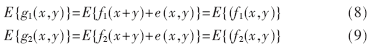
In the formula, E{g(x, y)} represents the average value of the gradation, f(x, y) represents the two-dimensional definition of the image, and e(x, y) represents the deviation function.
Equations (8) and (9) show that as the number of iterations increases, the average gray value will tend to be true. Therefore, the optimal value obtained by the iterative algorithm is not affected by noise interference.
In the calculation process, first select an approximation as the initial value, then perform segmentation to generate a sub-image; and select a new value according to the characteristics of the sub-image, and then divide the image with a new value, and after several cycles, the image segment is incorrectly segmented. The point is reduced to a minimum. The result of this is obviously better than the effect of directly segmenting the image with the initial value, and the improvement strategy of the value is the key to the iterative algorithm [7]. Specific steps are as follows:
(1) Select an estimate of the initial value
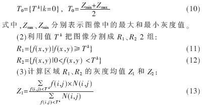
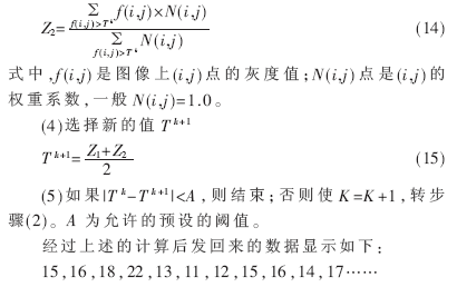
Through analysis, it is determined that 16 is a fixed threshold of the image. The experiment proves that the image after binarization with 16 threshold is relatively clear. Under the condition of good laboratory illumination, no discrete spots appear, and the self-identification effect of the smart car is very good. In the joint debugging process of software and hardware programs, in the normal lighting environment of the laboratory, the smart car can travel well along the line. In the actual debugging, it is found that if the light is too dark, the gray value of the graphic collected by the CCD camera will be biased. Low situation. In this case, you can try to use the fill light to meet the camera's requirements for ambient lighting. The smart car control system flow is shown in Figure 8.
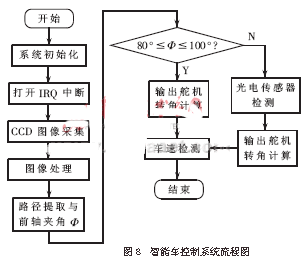
When the smart car is in straight running, the angle between the steering gear and the front axle is 90°. Considering the error of the deviation from the path during the running of the vehicle, when the angle range is between 80° and 100°, the steering gear is directly output. Calculated value; when the detected angle exceeds the range value, in order to ensure the correct driving direction of the smart car, the photoelectric sensor further detects the driving path and outputs the calculated steering angle.
The smart car is driving on a pre-set path. In the actual warehouse environment, because the smart car will have a large load, in order to ensure safety, when the smart car has a wrong situation, it must be forced to stop. It must be slowed down before reaching the cargo. Therefore, other equipment such as an infrared sensor and a travel switch can be installed for this situation to ensure that the detection information is sufficient for the smart car to drive safely.
In this paper, the AGV autonomously traces the smart car in the large warehouse to simulate the unmanned management of the warehouse. The feasibility of the smart car in this environment is proved by experiments. Based on the multi-sensor information navigation system, the intelligent vehicle unmanned management is realized in the large-scale warehouse management, which provides a useful reference for the industrial site multi-information navigation intelligent system.
This Lead Acid Battery Bank is a kind of mobile power bank and supply, it is also called Mobile Power Bank,Portable Power Bank and Battery Charge Pal. This battery energy power storage is used for DC consumer electronics products and other DC electronic machines. This rechargeable Lead acid battery bank is convenient, portable, long-lived and multifunctional. USB interface, solar charging input / DC input interface and automobile emergency startup interface are integrated on the surface of battery bank.
This Battery Energy Storage Power,Mobile Power bank and Battery Charge Pal is 280WH with Short-Circuit and Over-discharge Protection, Cut-off voltage is 10.5V (Besides 12V 300A output interface)
Application in DC Fan, Mobile Phone, DV, DVD, IPAD, Notebook PC, Computer, Nail Painting Machine, Inflator Pump, Washing Machine, Car Starter (Urgently), Lighting, Router, Monitor, DVR, MP3/MP4/GPS/, Radio, DC TV, DC Projector, Audio and other DC electric products.
This Multifunctional power charge pal now is wildly applied in Africa, America, Europe and Asia, When you encounter a shortage of electricity, you have it, so you don't have to worry about your working electricity, traveling power supply, or domestic family daily power, etc.
Specification:
USB Output:2PCS 5V2A
DC Output:4PCS 12V5A
DC Output:1PCS 19V4.7A
DC Output : 1PCS 12V300A
Solar Power Input:1PCS 18V50W
DC Input:1PCS 12V3A
Model:12V24AH(20Hr)
Caution
1)Car starting less than 5 sec. and input current less than 3A
2)Please recharge this battery every 2-3 months without any using
3)Do not short connecting 12V 300A interface
4)Battery charge current less than 4A, Do not use charger its charging current higher than 4A which damage your battery
Lead Acid Battery Bank
Lead Acid Battery Bank,Portable Battery Charge Pal
Shenzhen Daceen Technology Co., Ltd. , https://www.daceen-sz.com