IGBT (Insulated Gate Bipolar Transistor), or insulated gate bipolar transistor, is a composite power semiconductor device made up of BJT (bipolar junction transistor) and MOS (metal-oxide-semiconductor) structures. It combines the high input impedance of a MOSFET with the low on-state voltage drop of a GTR (bipolar transistor). This makes the IGBT highly efficient and widely used in various applications.

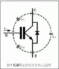
The IGBT integrates the benefits of both components, featuring low driving power and reduced saturation voltage. It is particularly well-suited for converter systems operating at DC voltages of 600V and above. Applications include AC motors, inverters, switching power supplies, lighting circuits, and traction drives. As shown in Figure 1, an N-channel reinforced insulated gate bipolar transistor has an N+ region known as the source region, with an attached electrode called the source. The N+ region is referred to as the drain region. The control area is the gate region, with its corresponding electrode being the gate. A channel forms near the boundary of the gate region. The P-type region (including P+ and P regions) between the drain and source, where the channel forms, is called the sub-channel region. The P+ region on the opposite side of the drain region is the drain injector, a unique functional area of the IGBT. Together with the drain region and sub-channel region, it forms a PNP bipolar transistor acting as an emitter. The drain injector injects holes and conducts charge carrier modulation to lower the on-state voltage of the device. The electrode attached to the drain implant region is called the drain. The switching operation of the IGBT involves forming a channel by applying a forward gate voltage, providing a base current to the PNP transistor, and turning on the IGBT. Conversely, applying a reverse gate voltage eliminates the channel and cuts off the base current, thus turning off the IGBT. The driving mechanism of the IGBT is similar to that of a MOSFET, requiring only control of the input pole N-channel MOSFET, giving it high input impedance characteristics. When the MOSFET channel is formed, holes from the P+ base are injected into the N layer, conductance modulation occurs, reducing the resistance of the N layer, and the IGBT maintains a low on-state voltage even at high voltages.

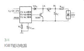
The role of the gate resistor Rg is crucial. First, it helps eliminate gate oscillations (or gate-source oscillations) in insulated-gate devices like the IGBT and MOSFET. These devices have a capacitive structure, and the parasitic inductance of the gate loop cannot be avoided. Without the gate resistance, the system would experience strong oscillations under the excitation of the driver's pulses. Therefore, a gate resistor must be connected in series to quickly dampen these oscillations. Second, the gate resistor reduces the power loss associated with the transfer driver capacitance and inductance, which are reactive components. If there were no gate resistance, much of the drive power would be consumed within the output tube of the driver, leading to significant temperature increases. Third, the gate resistor adjusts the on-off speed of the power switching device. A smaller gate resistance results in faster switching, minimizing switching losses but potentially increasing electromagnetic interference due to rapid voltage and current changes. Conversely, a larger resistance slows down the switching process, increasing losses but reducing interference. Therefore, a balance must be struck to optimize performance.

In summary, the IGBT is a remarkable advancement in power electronics, combining the best features of both BJTs and MOSFETs. Its ability to handle high voltages efficiently while maintaining low power consumption makes it indispensable in modern electronic systems. Proper selection and use of gate resistors play a critical role in ensuring optimal performance and reliability. Understanding the nuances of IGBT operation and its driving mechanisms can help engineers design more efficient and robust power conversion systems.
High Frequency Inverter Charger
High Frequency Inverter Charger,solar inverter charger,Inverter Charger,High Frequency Car Power Charger
SUZHOU DEVELPOWER ENERGY EQUIPMENT CO.,LTD , http://www.fisoph-power.com