The leakage switch tester commonly used by electricians at work is usually portable, compact, lightweight, and easy to carry. It can test various types of residual current devices (RCDs), making it the ideal tool for on-site or indoor inspections of RCDs. Advanced models typically display test results digitally, which is very convenient for both industrial plants and professional electricians.
A leakage switch tester is an electronic device built using integrated circuits, primarily used to measure the operating current, tripping time, and AC voltage of RCDs. Proper use of such tools can significantly enhance our efficiency at work. So, how do we effectively use a leakage protection tester? Let's first examine the diagram of the leakage switch tester, and then delve into its main functions.
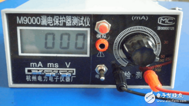
**Leakage Switch Tester Diagram**
The leakage protector, also known as a residual current device (RCD), is designed to prevent electric shocks and fires when a circuit or electrical insulation is damaged. The leakage switch tester is mainly used to test the leakage current of RCDs, including the leakage current and the tripping time. Both single-phase and three-phase RCDs can be tested.
Let’s take the M9000 leakage protector tester as an example. This tester doesn’t require an additional power source; it can run continuously for over 200 hours using just a 9V alkaline battery. The device comes with a case and a carrying bag, making it convenient for field tests.
**Main Technical Features of the Leakage Switch Tester:**
1. Display: Three-and-a-half-digit LCD display; features automatic temporary storage, lock, zero reset, overflow, battery replacement, and fuse blow indicators.
2. AC Leakage Current Measurement: Range: 0-500mA (with 500mA fuse). Accuracy class: 1.0, resolution: 1 mA.
3. Adjustable AC Leakage Current Measurement:
- Range: Type B 5-100, 100-200mA.
- Type C 5-100, 100-200, 200-300 mA.
4. AC Voltage Measurement: Range: 0-450V. Accuracy class: 1.5, resolution: 1V
5. Tripping Time Measurement: Range: 5-1000ms. Error: ±10%, resolution: 1ms.
6. Power Supply: DC9V±1V, power consumption: less than 20mw.
7. Operating Conditions:
- Temperature: Working range 0-40°C, extreme conditions: -10-50°C.
- Humidity: Working range 30°C (20-75%) RH.
- Frequency: Working range: 50±2.5Hz.
- Altitude: No more than 2000m.
- Avoid strong electric and magnetic fields, direct sunlight, and corrosive gases during use.
8. Dimensions: 165 × 120 × 60mm
9. Weight: About 0.5KG.
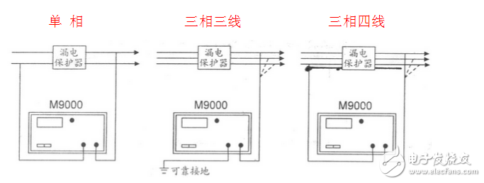
**Wiring Diagram for Leakage Switch Testers**
The illustration shows a switch-type protector. When testing a combined protector without a load, a test line must pass through the transformer of the protector; when using a load line, the test line does not need to pass through the transformer.
When performing a load test, another wiring method can be used: one test line is connected to one phase line in the load line after the protector; the other test line is directly connected to the ground line (body).
**How to Use the Leakage Protection Tester**
1. **Preparation Before Testing**: Before connecting the tester to the power supply, ensure the "power switch" is in the off position. The power supply should be connected to the power side of the RCD (AC220V). Ensure the phase and neutral wires are correctly connected. The test line passes through zero. The sequence transformer is connected to the phase line of the tester power supply. Place the tester function switch in the "pre-position". After confirming the wiring is correct, turn the "current adjustment" potentiometer on the tester panel counterclockwise to zero. Turn on the "power switch". At this point, the milliampere meter and millisecond meter readings should be zero. If not, press the "Reset" button.
2. **Leakage Protector Leakage Current Measurement (Load Side Lead Should Be Disconnected)**: Place the onboard function switch in the "pre-position". After inserting the RCD, press the "test" button. Slowly turn the "current adjustment" potentiometer clockwise. The tester's milliampere meter should show a milliampere value, gradually increasing until the RCD trips. The reading on the milliampere meter is the leakage current. Repeat the process to adjust the current until it reaches the specified value. Press the "Reset" button to return the current to zero, then press the "Test" button. If the RCD does not trip, it is considered qualified.
3. **Leakage Action Time Measurement (Load Side Lead Should Be Disconnected)**: Before measuring the tripping time, test the line from the RCD load to the power supply side of the main contact. Set the function switch to the "pre-position". Press the "Test" button, then turn the "Current Adjustment" potentiometer clockwise to adjust the current. Once the specified value is reached and maintained, disconnect the tester power switch. Change the test line to the RCD and the detector power supply phase main contact load side (do not connect incorrectly). Turn the function switch to the "test" position, close the RCD switch, and press the tester "power switch" (if the meter reading is not zero, press the "Reset" button). Press the "Test" button, the RCD should trip, and the millisecond meter display value is the tripping time under the specified leakage current. Press the "Reset" button to clear it, and repeat the above steps by reclosing the RCD.
4. **Leakage Current Measurement with Load**: The measured value is not the characteristic of the RCD but reflects the degree of three-phase leakage imbalance in the load. The measurement method involves connecting the tester power supply and test lines to the power supply side of each phase simultaneously, and measuring it using the aforementioned methods. Be cautious, as using three-phase wiring incorrectly could damage the tester.
**Measuring Leakage Current of Equipment Using a Leakage Protection Tester**
1. Press the "mA" (mA represents current) toggle switch on the leakage switch tester; then turn on the power switch of the leakage switch tester.
2. Ground the electrical equipment casing first, then connect the power cord of the electrical equipment to the red socket marked "Detection" on the tester panel, and at the same time connect the red-labeled socket to the power supply circuit in the tester panel. When powered on, the leakage current value will be displayed on the device display.
3. After the test is completed, remove the line and turn off the power switch.
**Measuring AC Voltage with a Leakage Protection Tester**
1. Press the "V" (V symbol represents voltage) toggle switch on the leakage switch tester, then turn on the power switch of the leakage switch tester.
2. Connect the detection port of the leakage switch tester to the circuit to be measured. At this time, the display shows the AC voltage value in the line.
3. After the detection is complete, remove the detection line from the circuit under test in time, and then turn off the power switch.
**Measuring Leakage Current of an RCD with a Leakage Protection Tester**
1. Press the "mA" (mA is the representative symbol of the current) gear switch, adjust the knob, rotate it counterclockwise, and then turn on the power switch of the leakage switch tester.
2. Connect the port on the leakage switch tester to the circuit under test.
3. Then close the circuit and the current value can be displayed on the display.
4. Then turn the (mA) adjustment knob slowly in a clockwise direction until the pointer rolls again. At this time, the action current value is displayed on the display.
5. After the test is completed, disconnect the circuit under test from the leakage switch tester and turn off the power.
**Measuring Differential Leakage and Electric Shock Current Protectors**
1. Press the "mA" gear switch.
2. Turn the "mA" adjustment knob counterclockwise to the end, and the range switch will still be placed in the 100mA position.
3. Close the leakage protector.
4. Turn the (mA) adjustment knob clockwise to make the current value display the action value of the leakage current of the leakage protector (about 50mA). This is a slow-change leakage preset.
5. Others remain unchanged, and the conversion direct key is turned into the "ms" mode.
6. After the automatic zero reset, press the “Analog†(electric shock) button, and the 50mA sudden (electric shock) braking time is displayed on the display.
Note: The preset value depends on the value on the leakage protector label.
**Using a Leakage Protection Tester - Important Notes**
1. The “Test Line L†and “Test Line N†must not be connected incorrectly. The red test lead corresponds to L (live wire), and the black test lead corresponds to N (ground). Sometimes a loose grounding connection can cause the test to fail. Pay attention to this distinction!
2. If the "On/Off" button is turned on and the indicator light is dim and the LCD screen is blank, it might be due to low battery. Use a Phillips screwdriver to open the battery cover on the back of the instrument and replace the battery with the same model (6V battery).
3. During use and transport, handle the device gently, avoiding strong impacts, vibrations, crashes, and exposure to chemical substances.
This comprehensive guide should provide you with all the necessary information to properly use a leakage protection tester. Remember, safety first!
Creative led display screen
LED DJ Display
LED DJ Booth is used different
product models and structures as different conditions, which can be
customized to the scene modeling. It can be spliced out the unique shape with
different sizes of triangles, rectangles, hexagon. Unique DJ Table is
not limited to kinds of environment. The application of the relevance and the
shape of DJ LED Video Wall can enhance scene recognition.
LED Bar Display will not
only present a delicate and realistic color performance through
the synchronization adjustment, but also is compatible with
different sources of input such as TVV, HDV, DVI, VGA, SDI. We adopt SMD technology
to achieve super-wide viewing angle and better surface
smoothness. Super light cabinet is to realize easy installation and
maintenance that can be customized for shapes, sizes, pixels, resolution.
LED DJ Display, LED DJ Booth, DJ LED Video Wall
Shenzhen Priva Tech Co., Ltd. , https://www.privaled.com