The most troublesome newcomer to the power supply just getting started is probably reading the circuit diagram. A few circuit diagrams are dozens of hundreds of devices, many people are very difficult to read, then there are some experiences and points to enable people to read and understand the contents of the fast circuit diagram? This article will be on the power supply The reading points of the circuit diagram are introduced and given examples.
A power circuit is a relatively simple but widely used circuit in an electronic circuit. When you get a power circuit diagram, you should follow the steps below to read and understand.
1 Firstly, according to the order of “rectification-filtering-stabilizationâ€, the whole power circuit is decomposed and analyzed step by step.
2 In the step-by-step analysis, the main circuit and auxiliary circuit, main components and secondary components should be distinguished, and their functions and parameter requirements should be clarified. For example, in a switched regulated power supply, the inductor and the freewheeling diode are the key components.
3 Because transistors have NPN and PNP types, some integrated circuits require dual power supplies, so a power supply circuit often includes different voltage values ​​and several sets of outputs. The values ​​and polarities of the output voltages of each group must be distinguished when reading the picture. Carefully distinguish the polarity of the transistors and electrolytic capacitors during assembly and repair to prevent errors.
4Familiar with some customary painting methods and simplified drawing methods.
5 Finally, the entire power supply circuit is fully integrated from front to back. This power circuit diagram is also understood.
Instance
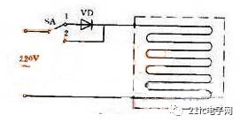
Figure 1 electric blanket circuit
Figure 1 is an electric blanket circuit. The switch is in the low temperature range at the "1" position. 220 volts power is connected to the electric blanket through the diode. Because it is half-wave rectification, the pulsating direct current of about 100 volts is applied to both ends of the electric blanket. The heat is not high, so it is in the state of heat preservation or low temperature. The switch is pulled to the "2" position, and the 220 volt mains is directly connected to the electric blanket, so it is a high temperature file.
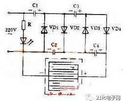
Figure 2 High-voltage mosquito killer circuit
Figure 2 shows a small-current DC high-voltage electric mosquito killer using the voltage doubler rectification principle. After 220 volts AC is rectified by quadruple voltage, the output voltage can reach 1100 volts, and this DC high voltage is applied to the parallel wire mesh. The bait is placed under the net, causing a short circuit when the fly stops on the net, and the high voltage on the capacitor kills the fly through the body discharge of the fly. After the fly corpse falls, the capacitor is charged again and the grid is restored to high voltage. This high-voltage grid has a small current and is therefore harmless to humans.
Because insects have phototaxis at night, if you put a 3 watt fluorescent lamp or a small black light behind the grid, you can trap mosquitoes and harmful insects.
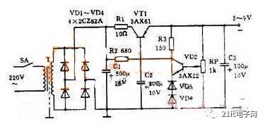
Figure 3 Practical regulated power supply
Figure 3 is a practical regulated power supply. The output voltage is adjustable from 3 to 9 volts and the output current is up to 100 mA. This circuit is a series-type regulated power supply circuit. To be careful of:
The drawing of the rectifier bridge is different from that of Figure 2(c). In fact, it is a bridge rectifier circuit.
2 This circuit uses a PNP-type manifold, so the output is a negative voltage and the anode is grounded.
3 Replace the Zener diode with two common diodes. The forward voltage drop of any diode is essentially constant, so a diode can be used instead of a Zener. The forward voltage drop of the 2AP type diode is about 0.3 volts, the 2CP type is about 0.7 volts, and the 2CZ type is about 1 volt. Two 2CZ diodes are used as reference voltages.
4 The sampling resistor is a potentiometer, so the output voltage is adjustable.
A circuit capable of amplifying a weak signal is called an amplifying circuit or an amplifier. For example, the key component in a hearing aid is an amplifier.
It can be seen that there is a certain way to read the circuit diagram without any obstacles and quickly understand the contents. First, it is necessary to perform general combing in the order of "rectification, filtering, and voltage regulation", and then subdivide each part, and finally serialize the contents of the entire picture.
Fast Recovery Diode,Ultra Fast Recovery Diode,Fast Recovery Rectifier Diode,Fast Recovery Epitaxial Diode
Shenzhen Kaixuanye Technology Co., Ltd. , https://www.iconlinekxys.com