introduction
ESP (Electronic Stability Program) is an iconic invention for automotive electronic control. Different R&D institutions have different names for this system, such as Bosch (Cars), which was called Automotive Dynamics Control (VDC) in the early days. Now Bosch and Mercedes-Benz are called ESPs; Toyota is called Car Stabilization. Sex Control System (VSC), Automotive Stability Assist (VSA) or Automotive Electronic Stability Control (ESC); BMW is known as Dynamic Stability Control (DSC). Although the names are not the same, they are based on traditional vehicle dynamics control systems, such as ABS and TCS, which add a lateral stability controller to control the distribution and amplitude of lateral and longitudinal forces in order to control the car in any road condition. Dynamic motion mode, which can improve the dynamic performance of the car under various working conditions, such as braking, slipping, driving and so on. ESP has been mass-produced abroad, and it is still in the research stage in China. To achieve the degree of industrialization, there is still a lot of work to be done.
This article refers to the address: http://
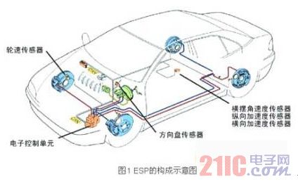
FIG. 1 is a schematic diagram showing the structure of an automobile ESP. The electronic components mainly include an electronic control unit (ECU), a steering wheel sensor, a longitudinal acceleration sensor, a lateral acceleration sensor, a yaw angular velocity sensor, a wheel speed sensor, and the like. ESP is an important electronic control system for ensuring driving safety. The normal operation of each sensor is the basis for effective control. This paper introduces the characteristics of ESP commonly used sensors, designs the sensor hardware interface and software interface, and is verified in the real vehicle test.
ESP common sensor introduction
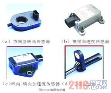
As shown in Figure 1 and Figure 2, the sensors commonly used in ESP are as follows.
a. Steering wheel angle sensor
The ESP identifies the driver's operational intent by calculating the size of the steering wheel angle and the rate of change of the corner. The steering wheel angle sensor converts the steering wheel angle into a signal representative of the driver's desired direction of travel. The steering wheel angle is generally determined by photoelectric coding. The code wheel mounted on the steering column contains the encoded rotation direction, corner, etc. information. The information on this encoder disc is scanned by a proximity optocoupler. After the ignition switch is turned on and the steering wheel angle sensor is rotated through a certain angle, the processor can determine the current steering wheel absolute rotation angle by the pulse sequence. The communication between the steering wheel angle sensor and the ECU is generally done via the CAN bus.
b. The yaw rate sensor yaw rate sensor detects the deflection of the vehicle along the vertical axis, and the magnitude of the deflection represents the stability of the vehicle. If the yaw rate reaches a threshold, indicating that the vehicle is experiencing a dangerous condition of slip or tail, the ESP control is triggered. When the vehicle is deflected about the vertical axis, the vibration plane of the microphonic fork in the sensor changes, and the yaw rate is calculated by the change of the output signal.
c. Longitudinal/lateral acceleration sensor
The acceleration sensor in the ESP has a longitudinal acceleration sensor along the advancing direction of the car and a lateral acceleration sensor perpendicular to the advancing direction. The basic principle is the same, but the installation is at an angle of 90°. ESP generally uses a micromechanical accelerometer. Inside the sensor, a small piece of dense material is attached to a movable cantilever that reflects the longitudinal/lateral acceleration of the car. The output is about 2.5V when static. Positive The acceleration corresponds to a positive voltage change, and the negative acceleration corresponds to a negative voltage change. Each 1.0 to 1.4V corresponds to an acceleration change of 1 g, and the specific parameters vary depending on the sensor.
d. Wheel speed sensor When detecting the wheel speed signal in a car, the most commonly used sensor is an electromagnetic induction sensor. The general method is to install the sensor on the non-rotating part of the wheel assembly (such as the steering knuckle or shaft head), along with the wheel. The ring gear made of the rotating magnetically permeable material is opposite. When the ring gear rotates relative to the sensor, an alternating voltage signal is excited on the sensor due to the change of the magnetic resistance. The frequency of the alternating voltage is proportional to the rotational speed of the wheel. The ECU uses a special signal processing circuit to convert the sensor signal into the same The square wave of the frequency is then calculated by measuring the frequency or period of the square wave.
In the original ESP system, the longitudinal/transverse acceleration sensor and the yaw rate sensor were implemented separately. Now, the sensor cluster mode is basically used, and the three sensors are designed as one body, and the CAN bus and the ECU are integrated. communication. Figure 3 shows the sensor assembly produced by SIMENS VDO and BEI.
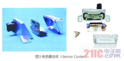
In order to add new ESP functions and to better control the stability system of the vehicle, such as Mountain Hold Control (HHC) and Line Control (SbW), Bosch proposed the concept of modular HW and SW and developed the third generation. Highly flexible and low cost chronic sensor assembly DRS MM3.x.
ESP common sensor interface design
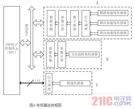
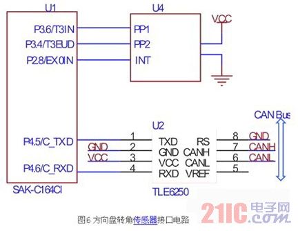
The block diagram of the design of this paper is shown in Figure 4. In the figure, the steering wheel angle sensor signal is processed by the microcontroller and sent to the ECU through the CAN bus (B in Figure 4); the yaw rate sensor and the longitudinal/lateral sensor are designed in the same way because of the similar signal characteristics and installation position. In the module (A in Figure 4); since the ESP has high requirements on the real-time performance of the wheel speed sensor signal, it is directly sent to the ECU (C in Figure 4) after signal conditioning. In A and B of Figure 4, the microprocessor is required to process the signal and transmit data through the CAN bus. This article uses Infineon's SAK-C164CI. Designed for automotive applications, the chip features an AD converter, input signal capture, and quadrature decoder for fast operation and is ideal for ESP sensor signal processing.
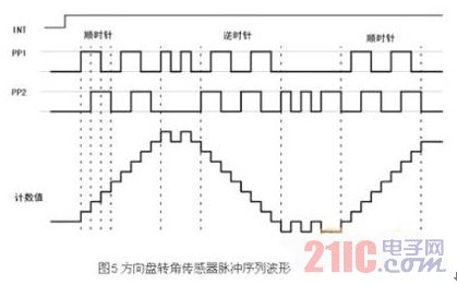
a. Steering wheel angle sensor interface The output of the steering wheel angle sensor is an orthogonal coded pulse. The orthogonally encoded pulse contains two pulse trains with varying frequencies and a fixed phase offset of a quarter cycle (90°), as shown in Figure 5. By detecting the phase relationship of the two signals, it can be judged as clockwise direction and counterclockwise direction, and according to this, the signal is added/down counted, thereby obtaining the current count cumulative value, that is, the absolute rotation angle of the steering wheel, and the change rate of the rotation angle. That is, the angular velocity can be measured by the signal frequency. In addition, the steering wheel angle sensor has a zero output signal. When the steering wheel is in the middle position, the signal outputs 0V, otherwise it outputs 5V. Through this signal, the absolute rotation angle can be calibrated online.
The interface circuit of C164CI and steering wheel angle sensor is shown in Figure 6. An on-chip incremental coded quadrature decoder is used. The decoder uses two pins of timer 3 (T3IN, T3EUD) as the input of the quadrature pulse. After the relevant register is correctly set, the data register of the timer 3 is The value is proportional to the steering wheel angle, so the angle can be conveniently calculated. The steering wheel angle sensor used in this paper corresponds to 44 pulses per cycle. If the data register of timer 3 is T3, the absolute rotation angle is.
By performing a differential operation, the rate of change of the corner can be obtained. The microcontroller sends the calculated parameters to the ECU via CAN.
b. Wheel speed sensor interface According to the characteristics of the wheel speed sensor signal introduced in the previous section, the design interface circuit is shown in Figure 7.
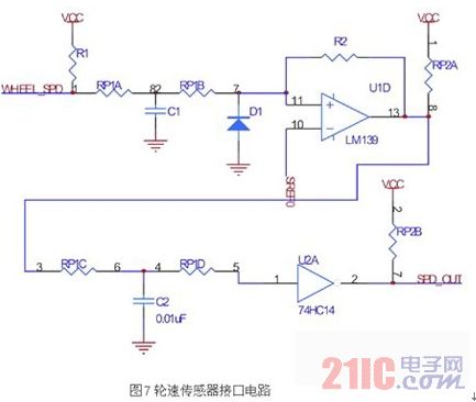
The circuit uses two levels of filtering and shaping to ensure that the wheel speed signal is not lost at very low speeds, while avoiding signal interference due to suspension vibration. The first stage hysteresis comparison is introduced by resistor R2 and the second stage hysteresis comparison is introduced using 74HC14.
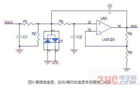
c. The yaw rate, the longitudinal/lateral acceleration sensor yaw rate, and the longitudinal/lateral acceleration sensor are basically the same. The output is 0V-5V. The signal fluctuation characteristics due to bumps in the car are the same, so they are packaged in the same module. . The hardware interface is shown in Figure 8. The hardware analog pre-filter is implemented to suppress the high-frequency noise components in the analog signal from the sensor to prevent aliasing during the sampling process. The op amp uses the LMX324 with rail-to-rail output.
By adjusting the parameters of each of the RC components in Figure 8, the filter cutoff frequency and delay size can be set. During the running of the car, when driving on a better road, because the signal is better, the delay should be as small as possible, and when driving on the bumpy road, the filtering effect is better. However, since the frequency characteristics of the hardware filtering are designed and cannot be modified in real time, it is necessary to design a digital filtering link in the software. Digital filtering commonly used are Wiener filters, Kalman filters, linear predictors, and self-applied filters. Here, the first-order low-pass filtering with small calculation amount and good real-time performance is selected.
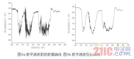
The choice of k depends on the current road surface condition, while the current road surface condition is identified by the original signal before digital filtering. The microcontroller packs the filtered signal, the original signal, the value of k, and the road surface recognition result, and sends it to the ECU through the CAN bus. Figures 9a and 9b are respectively a set of comparison curves of the longitudinal acceleration sensors collected in the actual road test of the bumpy road.
This paper discusses the structural characteristics and signal characteristics of commonly used sensors in ESP systems, and designs the signal processing interfaces of each sensor, including hardware interface circuits and software processing solutions. An integrated module including yaw rate and longitudinal/transverse acceleration sensors is designed to transmit data through the CAN bus and the ECU, which has better anti-interference and reliability. The design of this paper has been verified in the actual vehicle test.
Led Clock,Clock Light,Indoor Wall Light,Table Lamp With Clock
Guangzhou Huanyu Clocking Technologies Co., Ltd. , http://www.findclock.com