1 Introduction
This article refers to the address: http://
The TLV320AIC23 is a high-performance stereo audio codec from TI. It has a built-in headphone output amplifier that supports both mic and line in input methods. Both input and output have programmable gain adjustment. The TLV320AIC23's analog-to-digital converter (ADC) and digital-to-analog converter (DAC) are integrated inside the chip. Adopt advanced Σ one △ oversampling technology. Sample data of 16bit, 20bit, 24bit and 32bit can be provided at a sampling rate of 8kHz to 96kHz. The output signal-to-noise ratio of the ADC and DAC is up to 90dB and 100dB, respectively. Simultaneously. The TLV320AIC23 also has very low power consumption (23mW in playback mode and 15μW in power saving mode). These advantages make the TLV320AIC23 an ideal audio codec that complements TI's DSP family.
DSP/BIOS Driver Developer's Kit (DDK) is TI's driver development kit for simplifying driver development for the TMS320 family of DSPs and their EVM boards. The kit provides a complete, standardized driver model for the various peripherals of the TMS320 family, making it easy to port drivers to other applications, greatly improving driver development efficiency. The DDK complements the Chip Support Library (CSL) provided by each TMS320 series of DSPs. CSL provides low-level control of peripheral device register configuration and initialization. DDK completely controls peripheral devices through CSL. general speaking. DDK is built on top of CSL. So developing drivers with DDK will be faster and more portable.
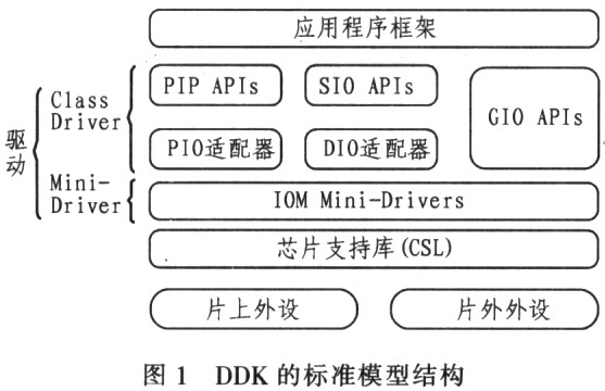
The DDK defines a standard model and a set of APIs for developing drivers. To simplify the programming. The standard model is divided into two levels. The upper level is called Class driver and the lower level is called Mini-driver. Class drivei is relatively independent of the device. Complete functions such as buffer management and request synchronization. At the same time, it plays the role of both API and Mini-driver. The Mini-driver performs specific device initialization and control functions. It complies with the interface standard of IOM (I/O Mini-driver). This hierarchical structure of the DDK allows the driver developer to understand the driver design of the overall peripheral device with only a single Mini-driver API, and this process is much simpler than designing the entire driver because the Class driver controls the buffer. Area management and synchronization, etc. DDK offers 3 Class drivers. They are SIO/DIO, PIP/PIO and GIO, all of which can be combined with any Mini-driver.
2 TLV320AIC23 drive design basis
The standard model structure of the DDK is shown in Figure 1. The high-level application and the underlying driver are not directly related to each other. In the development, only the Class driver is used to control the Mini-driver.
Take the DM642 EVM board as an example. Describe the driver design method of DDK-based TLV320AIC23.
First, you need to use the configuration tool to build the driver entry. In the cdb file under DSP/BIOS con_fig. Select In-puffOutplut---Deviee Drivers→User→defined Drivers. udevCodec has been added to these routines. Users can add or edit them themselves if needed. Right click and select the Properties option to edit its properties. The properties should be set as follows:
Comment: You can add your own comments
Lnit function: type EVMDM642_EDMA_AIC23 an init
Function table ptr: Type EVMDM642_EDMA_A-IC23-Fxn8
Function table type: Select IOM_Fxns
Deviceid: This item will be automatically ignored. Because there is only one TLV320AIC23 on the DM642 EVM board.
Device params ptr: The entry pointer of the TLV320AIC23 parameter structure. Set to 0x0 when using default parameters
Device global data ptr: Must be set to OxO
After properly configuring the driver entry. It is necessary to set the relevant parameters as needed. The setting of the TLV320AIC23 parameter is discussed in detail below.
The parametric structure of the TLV320AIC23 is as follows:
Typedef struct
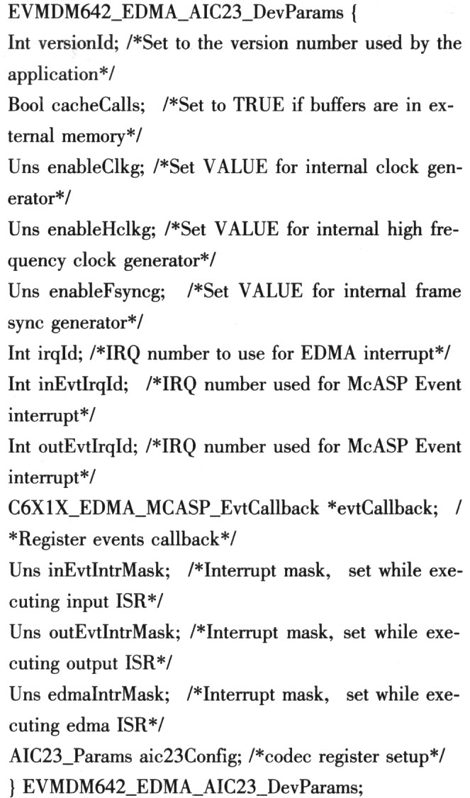
In general applications. Most of the parameters of the above structure do not need to be changed, and the main need to be modified is aie23Config. It is the TLV320AIC23 control register value. It is necessary to control the TLV320AIC23's working mode, input/output selection, sampling rate and other important parameters.
In addition to the reset register. TLV320AIC23 has a total of 9 control registers. Each register control word length is 9bit. The address bit is 7 bits and has a total of 16 bits. The address bits are the upper 7 bits and the control word is the lower 9 bits. details as follows:
Register0: Left channel input volume control, default is 0x0017
Register1: Right channel input volume control, default is 0x0017
Register 2: Left channel output volume control. The default is Ox01F9
Register 3: Right channel output volume control, default is Ox01F9
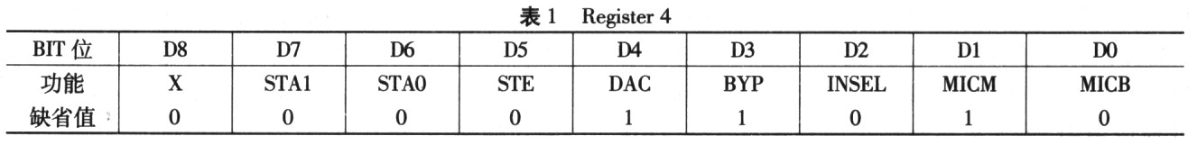
Register 4: Analog audio channel settings. The default is Ox0011
Register 5: Digital audio channel settings. The default is 0x0000
Register 6: Power saving mode control. The default is 0x0000
Register 7: Digital audio interface format control, default is 0x0043
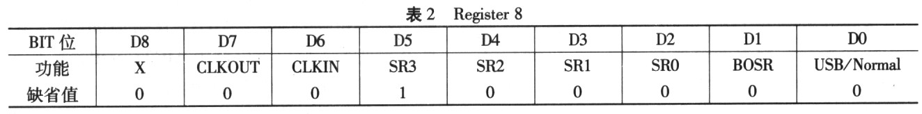
Register 8: Sample rate control, default 48kHz, for the DM642EVM board. The default is Ox0002
Register 9: Digital audio interface activation switch. The default is 0x0001
Registers that need to be modified normally include registers 4 and 8. That is to choose whether to input by mic or by line in and select the sampling rate as needed. The detailed configuration of these two registers is as follows:
The configuration of the 4th register is shown in Table 1, where the D2 bit. INSEL (In-put select for ADC) is the input selection, "O" is line in; "l" is mic.D1 bit MICM (Microphone mute) is mic mute switch. Mute for "l". Setting the DO bit MICB (Microphone boost) to "1" will provide 20dB of gain for the mic input. The configuration of the 8th register is shown in Table 2, where the sampling rate control bits are SR[3:O] of D5~D2. For the DM642 EVM board, the setting method is shown in Table 3.
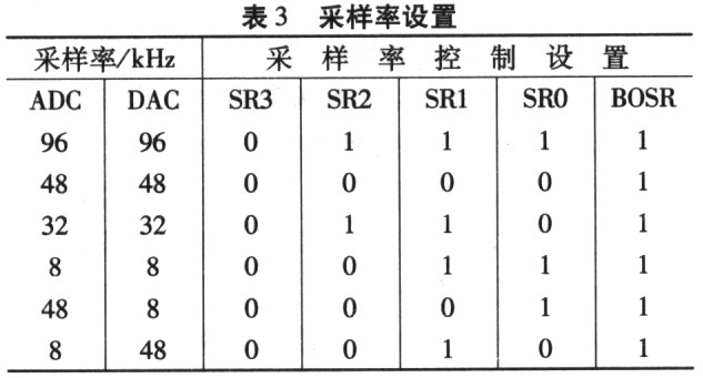
visible. It is necessary to select the input through D2 of the 4th register, and consider the control of mic by Dl and DO; the control of the sampling rate is realized by setting SR[3:0] of the 8th register.
3 TLV320AIC23 driver configuration method
The most common problem for many beginners when running the DM642 EVM echo or other audio routines is the output when inputting through line in. There is no output when inputting through mic, let alone changing the sampling rate. Even the reference edit aic23-h and emvdm642_edma_aic23. h Modifying the Dcfauh parameter still does not solve.
When such a problem occurs. The first thing to understand is that the analog audio input of the TLV320AIC23 is mic and line in, and secondly, how to properly configure the parameters of the TLV320AIC23 to meet the needs of specific applications. If you carefully analyze the echo routines and other audio routines, you can see that only the aie23.h and emvdm642_edma_aie23 are included in the echo routine. h 2 header files. In fact, in the echo routine. The two header files included and the initialization statement of TLV320AIC23 are not actually used. If you mask out the inclusion of these two header files and the initialization statement of TLV320AIC23, you will find that it still works normally after compilation. In fact, the TLV320AIC23 initialization statement in the echo routine only provides a way to configure II, V320AIC23 and is not directly used. This method has also been mentioned in the emvdm642 part of the DDK package.
Since the driver population is initialized in the echo routine with the same default parameters as the other audio routines, the default parameters are obtained by calling the evmdm642_edma_aic23.164 library in the DDK package. If the library is unchanged, the configuration will not change, and the above problem will occur.
After clearing the above principles. Through practice, the following three configuration methods provided in this paper can be adapted to various applications.
method one
Since the default parameters are obtained by calling the evmdm642_edlna_a-ic23.164 library. Naturally, you can modify the library to achieve the purpose of modifying the parameters. The DDK package provided by TI contains the source code of various libraries. This makes it possible to modify the library file. The library generation project used in this article is evmdm642_edma_mc23_64 in the tiddksrc\audio\evmdm642 directory. Pjt, just open the project. Modify one of them aic23. The default parameters in h, recompiled to generate a new library file. This way, all audio routines will run by default with the modified parameters.
This method is suitable for applications where the TLV320AIC23 parameter configuration is relatively fixed. Configuration is done entirely by calling the evmdm642_ed_ma_aic23.164 library initialization. No need to add any additional code to the application project file. Make the project file more concise. More portable.
Method Two
Custom-compliant standard structure EVMDM642_EDMA_A. The structure of IC23-DevParams, for example:
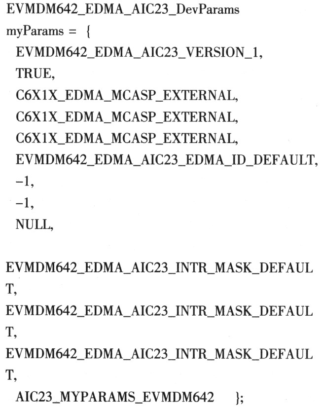
Then use "_myParms" as Device params ptr instead of the default 0x0 when specifying the population pointer. This is in line with TI's recommended method, and the relevant code in the echo routine also illustrates this approach.
This method can adapt to almost any use case, the initialization parameter customization is very clear, and the code is more legible. However, header files that contain default parameters directly as in the echo routine are not recommended. It is best to define your own structure with reference to this header file.
Method three
By carefully analyzing the source code of the evmdm642_edma_aic23.164 library, it can be found that the setting of the TLV320AIC23 register is done by the AIC23_setParams() function. In most cases, it is only necessary to modify the register values ​​without modifying other variables in the standard structure EVMDM642_EDMA_AIC23_DevParams structure. So you can call the AIC23_setParams() function to complete the configuration of the TLV320AIC23 parameters. This only requires defining a register array that conforms to the standard. Calling the AIC23_setParamsf() function with the array name as a parameter will do the trick.
This method is flexible, the code length is very short, the meaning is very clear, and can be called multiple times with different parameters. Especially suitable for special occasions where the TLV320AIC23 parameters are variable.
4 Conclusion
Based on the actual work, the author puts forward three methods for the parameter configuration of TLV320AIC23, each with its own characteristics and very practical. When designing the DDK-based TLV320AIC23 driver. Can be easily selected as needed.
- 20A 120VAC Two Tamper-Resistant (TR) receptacle enhance electrical safety, preventing objects from being inserted into the outlet
- The USB Ports are Class 2.0 and feature a combined power of 5Vdc,3.1 Amps
- Terminal screws accept up to 10AWG copper or copper clad wire
- The USB charge receptacle is to be installed in a wall box measuring at least 3"X2"X2-1/2", and wired in accordance with NEC acticle 314 box fill requirements
-
UL & CUL listed
- With a wall plate
4A USB TR UL,High Speed 4A USB TR UL,Universal 4A USB TR UL,Electrical 4A USB TR UL
Hoojet Electric Appliance Co.,Ltd , http://www.hoojetgfci.com