1. Soldering irons can be classified into two types based on their heating method: internal-heating and external-heating. The internal-heating type has high thermal efficiency (up to 85%-90%), a fast-heating tip, high temperature, compact size, and light weight for the same power. However, it is prone to oxidation and burning of the tip during prolonged use, leading to a shorter lifespan. It is not suitable for high-power applications. On the other hand, external-heating soldering irons are more durable, have stable temperatures during long working hours, and are less likely to damage components during soldering. However, they are bulkier and less thermally efficient.
2. Commonly used resistor values follow standard series such as E48, E24, E12, and E6.
3. Resistors are marked using various methods, including the straight label method, text symbol method, digital representation method, and color code method.
4. Manual soldering tools include electric soldering irons, electric air guns, and soldering stands. Automatic welding equipment includes wave soldering machines and reflow soldering machines.
14. Common anti-interference measures include shielding, decoupling, frequency selection, filtering, and grounding.
16. The assembly process of electronic products involves preparation, assembly, debugging, inspection, packaging, and storage or delivery.
17. Safety inspection of electronic products mainly focuses on insulation resistance and insulation strength.
18. The production of electronic products covers the entire development, design, and launch process.
19. Design documents typically include circuit diagrams, assembly drawings, wiring diagrams, functional descriptions, and component lists.
20. Design documents are categorized based on content (drawings, sketches, texts, tables), formation process (trial production and production documents), and usage characteristics (sketches, original drawings, base maps, and program-containing media).
21. The debugging process of electronic products includes pre-power-on inspection, power-on testing, and machine testing.
22. Fault-finding and troubleshooting steps generally involve observation, testing, analysis, fault identification, problem-solving, and performance checks.
23. Common methods for fault finding include the observation method, measurement method, signal method, comparison method, replacement method, heating and cooling method.
24. From a microscopic perspective, the soldering process consists of three stages: wetting, diffusion, and joint formation.
25. Wave soldering features high productivity, making it ideal for large-scale single-sided PCBs. It allows precise control over temperature, time, solder, and usage. However, it may cause bridging between solder joints, requiring repairs.
26. To detect resistors, capacitors, inductors, diodes, switches, and speakers with a multimeter:
- Resistance: Use the ohmmeter function.
- Capacitance: Use the highest resistance range on an analog multimeter.
- Inductance: Measure with a 1Ω or 10Ω range. If the measured resistance is much higher than nominal or infinite, it indicates an open circuit. A lower value suggests a short.
- Diode: Forward resistance should be low, reverse resistance high. A difference of several hundred times indicates good unidirectional conductivity.
- Switch: Check insulation and contact resistance with the ohmmeter. Mechanical switches should have insulation resistance below several hundred kΩ and contact resistance above 0.5Ω.
- Speaker: Use the 1Ω range to measure DC resistance. If it's lower than nominal, it’s normal. If higher, there may be an internal break. A good speaker will produce sound without distortion.
Part drawing: Start by understanding the name, material, scale, dimensions, and purpose from the title bar. Then analyze the general shape using the views and apply shape and line-surface analysis to determine the structure.
Block diagram: Read from left to right or top to bottom, following the signal flow. Understand the names, symbols, functions, and relationships of each part to grasp the overall composition and functionality of the product.
Electrical schematic: Begin by understanding the role, characteristics, and technical specifications of the product. Follow the block diagram from input to output, analyzing each unit circuit to understand the connections and working principle.
Assembly drawing: Start with the title bar to identify the name and number. Check the detail column for part information, locate them in the assembly, and analyze their positions and connections. Finally, assemble according to the drawing and process instructions.
Wiring diagram: Review the title bar and schedule, then refer to the electrical schematic to understand the wiring layout and connect wires to the correct positions as per the process documentation.
Printed circuit board assembly drawing: Must be read alongside the electrical schematic. Identify key components, locate the ground terminal, and follow the reading direction to complete the interpretation of the PCB assembly drawing.
31. Technical requirements for component lead forming include: no cracks or surface damage, no deformation exceeding 10%, markings must be visible and consistent, and avoid placing any excavation points near the fusion point.
32. Precautions for soldering iron detection, maintenance, and use include: checking for loose connections and damaged cords, cleaning the tip before first use, avoiding placement on hot surfaces, not striking the iron, turning off when not in use, and proper cooling after use.
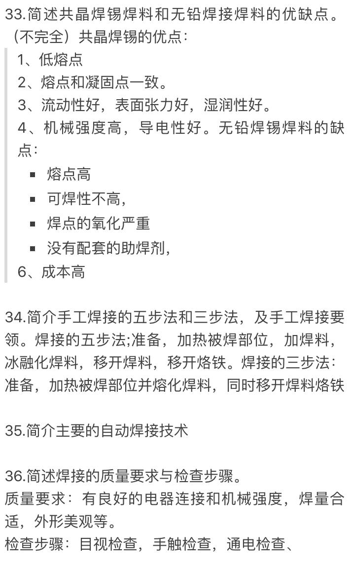
37. Lead-free soldering technology offers environmental benefits but requires higher melting temperatures and may reduce joint reliability compared to traditional lead-based solder.
38. Component selection in electronic production is based on schematic specifications, ensuring performance alignment while considering cost and availability. Components should be reliable, easy to source, and meet technical requirements.
39. Technical requirements for component mounting on printed boards include correct orientation, proper polarity, uniform height, logical installation order, even distribution, appropriate clearance, and special handling for specific components.
40. The production process of printed circuit boards includes base film processing, graphics transfer, etching, mechanical processing, and quality inspection. Inspection methods include visual inspection, connectivity tests, insulation resistance tests, and weldability tests.
41. Design requirements for electronic product structures include functional performance, compactness, ease of use, safety, ease of assembly, and suitability for mass production.
42. Final assembly of electronic products involves combining parts, subassemblies, and units into a complete system. The order follows principles like light to heavy, small to large, and inside to outside. Assembly must ensure cleanliness, correct installation, and functional integrity.
43. Electronic product assembly levels include component-level, plug-in assembly, and system-level assembly, representing increasing complexity and integration.
44. Quality inspection of electronic assemblies includes appearance checks, correctness verification, safety testing, and functional testing to ensure compliance with design standards.
45. Process documents guide production based on design documents. While design documents define the product, process documents specify how to manufacture it, ensuring consistency and efficiency.
46. Process document preparation should consider product complexity, available equipment, worker skill levels, and industry standards. Documents must be clear, accurate, and practical for production use.
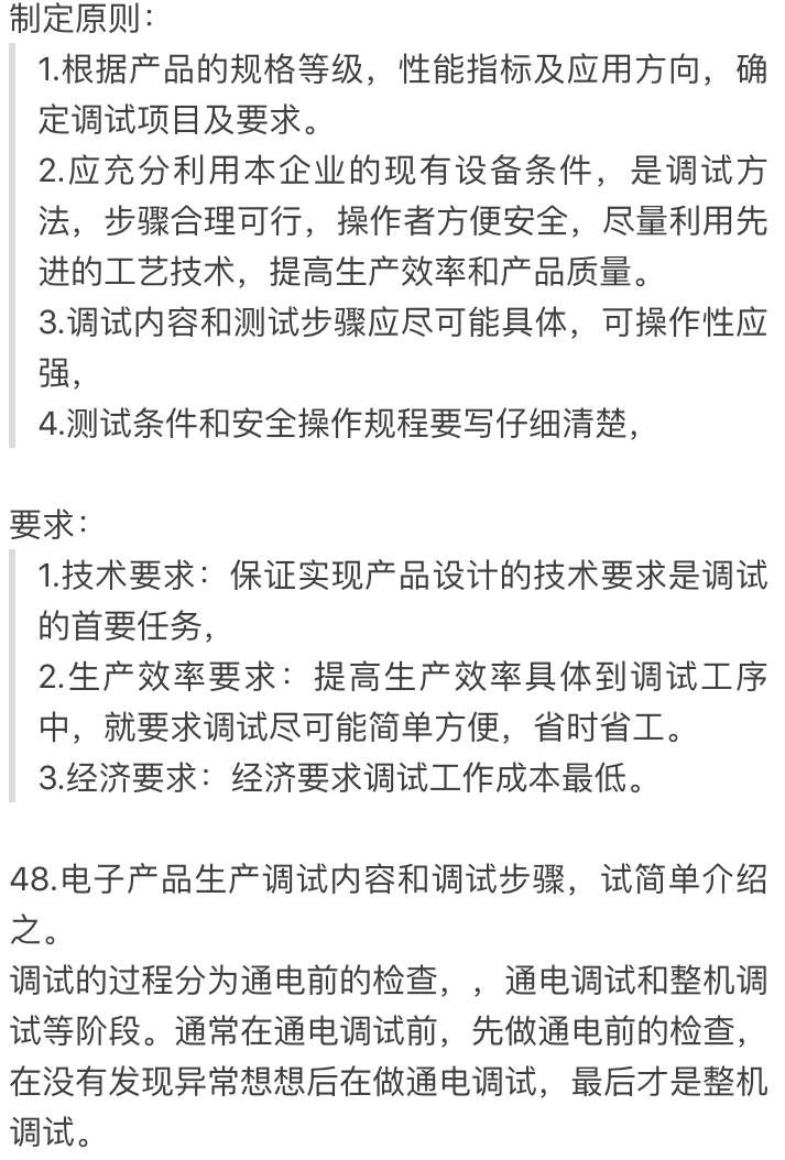
47. Commissioning process documentation and plans must outline procedures, tools, and safety protocols to ensure smooth operation and reliable performance of the final product.
49. Commissioning principles include starting with the power supply, then moving to other circuits, block-by-block testing, and prioritizing electrical over mechanical adjustments.
50. Static testing methods include direct and indirect approaches. Direct testing involves measuring current directly, while indirect testing uses voltage measurements converted to current values.
51. General fault-finding techniques include observation, measurement, signal injection, comparison, replacement, heating/cooling, and computer-assisted diagnostics.
52. Key steps in ferrochrome soldering include preparation, mastering soldering techniques, selecting the right iron, controlling time and temperature, and cleaning and inspecting the joint after soldering.
Black safety cone road cone,Black Omnidirectional Antenna,Black Transmitting Antenna
Mianyang Ouxun Information Industry Co., Ltd , https://www.ouxunantenna.com