1. Soldering irons can be classified into two types based on their heating method: internal-heating and external-heating types. Internal-heating soldering irons have high thermal efficiency (up to 85%-90%), fast tip heating, high temperature, compact size, and light weight for the same power rating. However, they are prone to oxidation and burning of the tip due to concentrated heat during use, which shortens their lifespan and makes them unsuitable for high-power applications. On the other hand, external-heating soldering irons are more durable, have a longer service life, maintain stable temperatures during prolonged use, and are less likely to damage components during soldering. Their main disadvantages include larger size and lower thermal efficiency.
2. Commonly used resistor values follow standardized series such as E48, E24, E12, and E6. These series define the nominal resistance values available in the market, ensuring consistency and compatibility across electronic designs.
3. Resistors are typically marked using several methods: direct labeling, text symbols, numerical representation, and color coding. Each method has its own advantages depending on the application and space constraints.
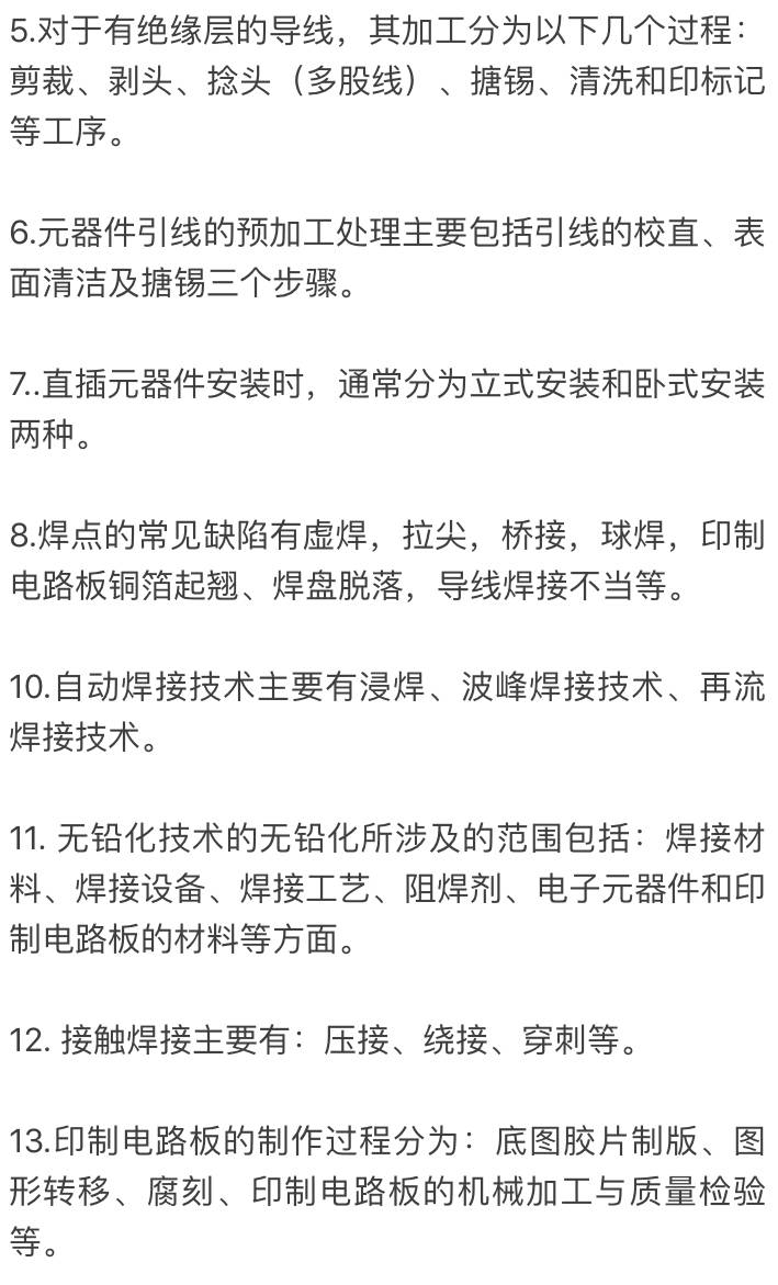
4. Manual soldering tools commonly used include electric soldering irons, air guns, and soldering stands. Automatic soldering equipment includes wave soldering machines and reflow ovens, which are ideal for mass production and complex PCB assemblies.
14. Common anti-interference measures include shielding, decoupling, frequency selection, filtering, and grounding. These techniques help reduce electromagnetic interference and ensure stable operation of electronic devices.
16. The assembly process of electronic products involves preparation, assembly, testing, inspection, packaging, and storage or delivery. Each step is crucial to ensuring the final product meets quality and performance standards.
17. Safety inspection of electronic products mainly focuses on insulation resistance and insulation strength, ensuring the device is safe for use under various conditions.
18. The production of electronic products refers to the entire process from product development, design, and launch to manufacturing and distribution.
19. Design documents typically include circuit schematics, assembly drawings, wiring diagrams, function descriptions, and component lists. These documents serve as essential references for both design and manufacturing.
20. Design documents can be classified by content (drawings, sketches, texts, tables), by stage of creation (trial production vs. production documents), and by usage (sketches, original drawings, base maps, etc.).
21. Electronic product debugging involves pre-power-on inspection, power-on testing, and machine-level testing. Each phase ensures that the circuit functions correctly before final deployment.
22. Fault-finding and troubleshooting in electronics usually involve observation, testing, analysis, and correction. This systematic approach helps identify and resolve issues efficiently.
23. Common fault-finding techniques include visual inspection, measurement, signal injection, comparison, replacement, and temperature control. These methods help pinpoint problems in complex circuits.
24. From a microscopic perspective, the soldering process consists of three stages: wetting, diffusion, and joint formation. Understanding these stages is key to achieving strong and reliable solder joints.
25. Wave soldering is efficient for large-scale single-sided PCBs, allowing precise control over temperature, time, and solder usage. However, it may cause bridging between solder joints, requiring post-soldering inspection and repair.
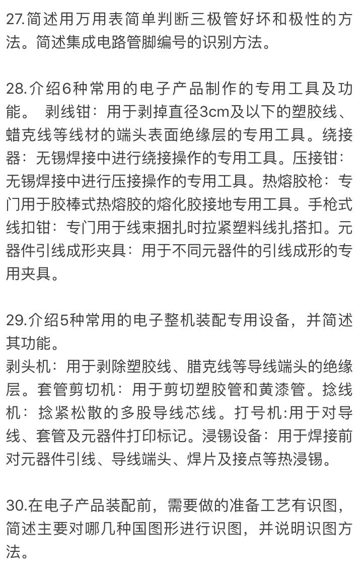
26. Using a multimeter, you can test resistors, capacitors, inductors, diodes, switches, and speakers. For example, resistors are measured with the ohmmeter function, capacitors with an analog meter, and diodes by checking forward and reverse resistance.
Part drawings provide details about the name, material, scale, and dimensions of a part. Block diagrams show the overall system structure, while electrical schematics detail the connections and functions of each component. Assembly drawings guide the placement of parts, and wiring diagrams show how components are connected. Printed circuit board assembly drawings must be read alongside the schematic to understand the layout and connections properly.
31. Component lead forming should meet technical requirements: no cracks or damage to the component body, no deformation exceeding 10%, and markings should be clearly visible for easy identification and maintenance.
32. When using a soldering iron, regular checks and maintenance are essential. Before first use, clean the tip and apply tin to prevent oxidation. During use, avoid dropping or shaking the iron, and always place it on a stand when not in use. After use, turn off the power, let it cool, and clean the tip.
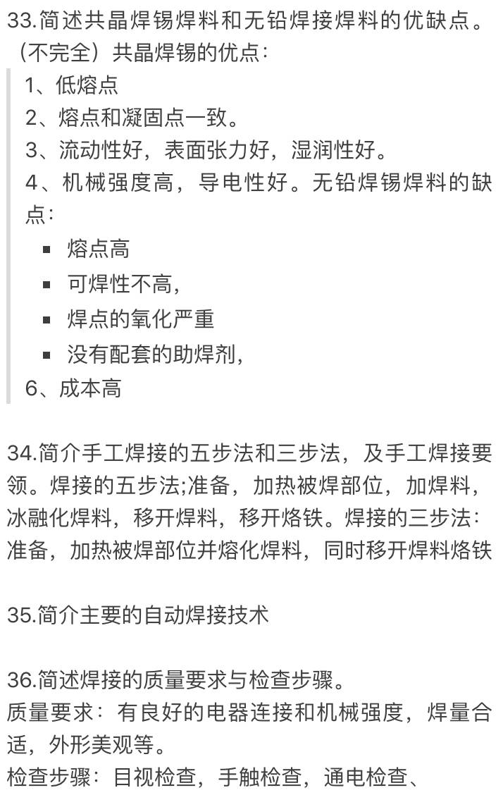
37. Lead-free soldering offers environmental benefits but has challenges like higher melting points and potential for cold solder joints. It requires careful control of temperature and technique to ensure reliability.
38. Component selection in electronic production is based on the design specifications, with a focus on meeting functional and technical requirements. Components should be selected to minimize complexity, ensure quality through testing, and balance cost-effectiveness.
39. During printed board assembly, components must be placed according to the design, with correct polarity, height, and spacing. Uniformity, neat arrangement, and proper lead-to-hole clearance are important for reliability and aesthetics.
40. The production of printed circuit boards involves base film processing, image transfer, etching, mechanical processing, and quality inspection. Inspection methods include visual checks, connectivity tests, insulation resistance tests, and weldability tests.
41. The structural design of electronic products must ensure functionality, reliability, compactness, ease of use, safety, and ease of assembly and maintenance. It should also support mass production and automation.
42. Final assembly involves putting together all components, including PCBs, panels, and connectors, to form the complete product. The order follows principles like small to large, light to heavy, and inside to outside. All components must be clean, correctly positioned, and free from damage during assembly.
43. Electronic assembly can be divided into three levels: component-level (lowest level), plug-in-level (board-level), and system-level (device-level). Each level builds upon the previous one to form a fully functional product.
44. Quality inspection of assembled electronics includes visual checks, correctness verification, safety testing (insulation resistance and strength), and functional testing. Ensuring all aspects meet standards is critical for product reliability.
45. Process documents and design documents both guide production, but they differ in purpose. Design documents are the original basis, while process documents outline the specific steps and methods to achieve the design intent.
46. Preparing process documents requires following standard formats, ensuring clarity, and aligning with national and industry standards. They should be detailed enough to guide workers without being overly complex.
47. Commissioning process documentation and plans must be clear, covering all necessary steps for testing and adjusting the product. They should include instructions for troubleshooting and verifying performance.
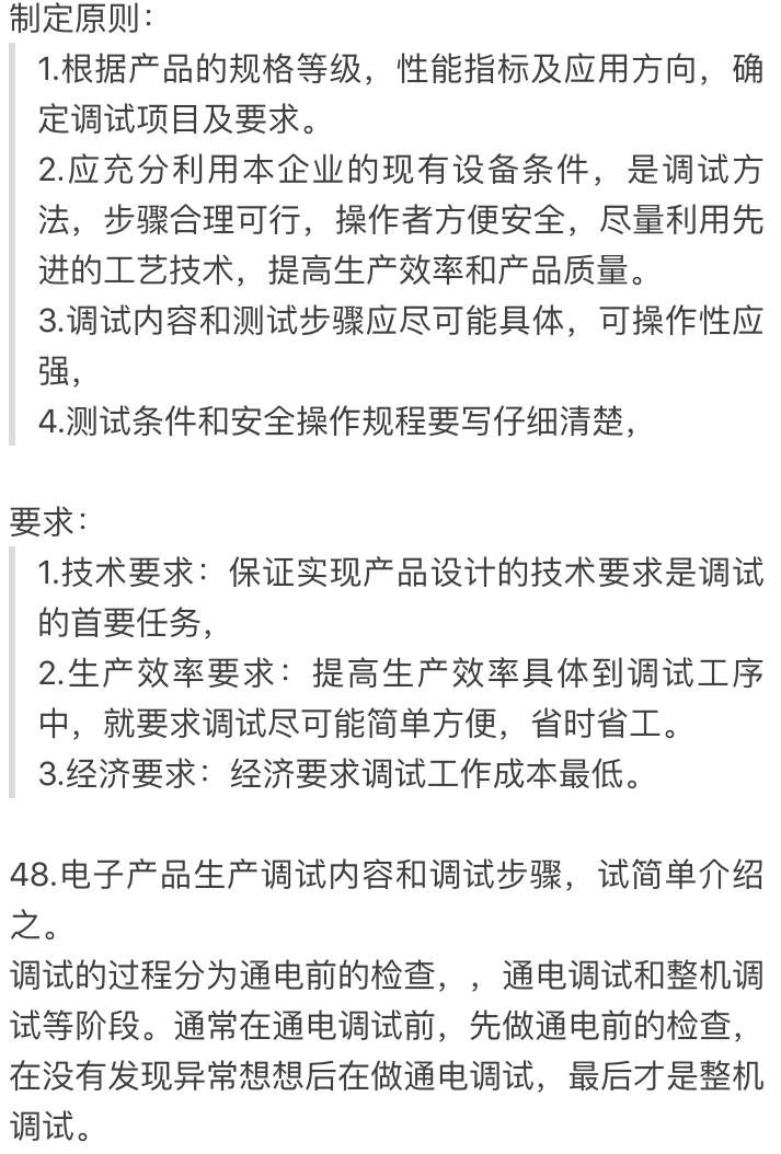
49. The commissioning process follows principles such as starting with the power supply, then testing individual blocks, and finally integrating the mechanical and electrical parts. This structured approach ensures a smooth start-up and stable operation.
50. Static testing methods include direct and indirect approaches. Direct testing uses current measurements, while indirect methods measure voltage and convert it to current for analysis.
51. Common fault-finding methods include observation, measurement, signal injection, comparison, replacement, and temperature control. These techniques help identify and resolve issues quickly and effectively.
52. The essentials of soldering include preparing the workspace, mastering the soldering technique, selecting the right iron, controlling time and temperature, and cleaning the joint after soldering to check for defects.
Car Antenna,Disk Cone Antenna,Airborne Antenna
Mianyang Ouxun Information Industry Co., Ltd , https://www.ouxunantenna.com