Here to share with you to learn 51 single-chip experience:
1. I never say that 51 is the foundation. If I say this, please understand this sentence as the basis of the microcomputer principle.
2. The operation of the 51 MCU is essentially the operation of the register, as is the case with other MCUs. The library is just an interface that is easy for the user to use.
3, assembly language is rarely used in the work, just understand.
4, 51 MCU's P0 port is very special.
5, C language is C language, 51 single-chip is 51 single-chip, the algorithm is the algorithm, the peripheral circuit is the peripheral circuit, the sensor is the sensor, the communication device is the communication device, the circuit diagram is the circuit diagram, the PCB diagram is the PCB diagram, the simulation is the simulation.
When you don't use 51 again in the future, the knowledge of C language is still there, the knowledge of the algorithm is still there, the skill of setting up the minimum system of the single chip is still in use, the method of using the sensor and communication device is still in use, and the circuit diagram and PCB drawing are also drawn. Of course, it will also simulate.
6, 51 MCU is this:
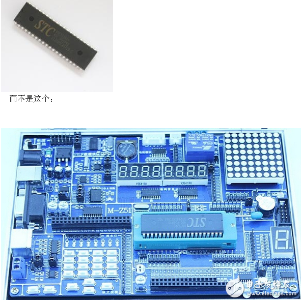
7, when the program debugging is not satisfactory, calm down to check the information, the biggest advantage of 51 MCU is that there are a lot of online information, and you have encountered problems that others have encountered. As a learner, asking people may be more convenient, but this has always been the ability to solve problems.
8, some single-chip beginners feel that the routine is not good, I feel that it is equivalent to see the answer is just guilty. In fact, for beginners, it is the best way to learn how to understand the routines and then look at the routines. It is also possible to transplant the program when doing the experiment design and doing the entry, and you don't need to reimplement it yourself. (Of course, the homework assigned by the teacher is still completed independently)
However, it is important to understand that porting a program is not equivalent to learning a microcontroller. The most important thing is to know what kind of framework and implementation method the routine is. Which registers are initialized, which pins are configured, which functions are called, how those functions are implemented, which interrupts are set, which on-chip resources (UART, ADC, etc.) are used, which states are queried, if the state changes (triggering events) what else to do and so on. This sorts out a flowchart and knows how it is implemented. Basically, this routine learns almost.
Summary 51 single-chip pull-up resistor
(1) Used to provide drive capability for OC and OD gate circuits.
Take the OC (Open Collector) circuit as an example:
For example, the Darlington tube (in fact, the composite three-stage tube) integrated block ULN2003. The internal circuit is shown as an open collector circuit.
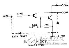
If you do not add a pull-up resistor, you cannot drive other devices at a high level. Because when the triode ends up there is no path for current circulation, it is hard to say that it is driven. This is the same principle as the pull-up resistor of the P0 port of the microcontroller.
(2) Increase the high level potential:
The M1 P1 port is connected to the 4&TImes; 4 matrix keyboard. In addition, the P1.0~P1.3 external ULN2003 control drive stepper motor is multiplexed.
Problems encountered in the experiment: When the ULN2003 is connected, the keyboard cannot work. After removing the ULN2003, the keyboard works normally. ULN2003 is working properly. (Note that the two parts do not work at the same time)
Problem Analysis: Due to the structure of the keyboard, nothing more than the opening or opening of two metal pieces. However, after accessing ULN2003, it cannot work normally, indicating that access to ULN2003 has affected the change of the P1 port level. When using a multimeter to measure the voltage, when the microcontroller outputs a high level, P1.0 ~ P1.3 voltage is about 1V, P1.4 ~ P1.7 voltage is about 4.3V, so the AT89s52 high and low level decision potential is measured, around 1.3V . In this way, P1.0~P1.3 is always low level, and the keyboard cannot realize the scanning function at all.
The solution, as long as the potential of the P1 port is raised, it can work normally.
1. Connect the resistor in series from the P1 port to the ULN2003 to play the role of voltage division, and then raise the high level.
2. Connect the pull-up resistor to the P1 port, and connect it with the internal resistance of the P1 port to reduce the resistance of the pull-up resistor and reduce the divided voltage, thus raising the high-level potential of the P0 port.
The second scheme can be used to raise the high level to about 2.5V. The keyboard works fine.
In addition: When I was doing LCD display experiment, the P0 port used for the data line could not work normally and no characters were displayed. But the display can be completed by tampering with the data line, but the display phenomenon is not normal. The character is not written once, but it can be written several times to write the entire content. Normally, it should be displayed all at once. The reason is because there are six ports in my P0 port that are connected in parallel with three LEDs. Because it is found from the data, each port of P0 port can absorb 10MA current at maximum, and the total current can't exceed 26MA current. This counts my total current has reached 40MA, huh, huh. I laughed. So doubt is the problem of driving. So several diodes were removed. Show everything is ok. It seems that the problem has been solved, but it always feels a bit problematic, so after several experiments, it is found that only when the parallel diode of the P0.7 port is removed, and then an LED is connected to the other port. This can also be displayed normally. However, the P0 port absorbs current at 38MA, which is also more than 26MA. So it is not a problem of absorbing too much current. Careful analysis when the port is connected in parallel with three diodes is equivalent to adding a resistance of about 700 ohms, so the diode is removed and replaced with a 1k resistor, the liquid crystal can not be displayed.
After careful analysis, I believe that since P0.7 is the return line of the LCD busy signal, when this port returns to high level, the LCD is processing data and cannot receive new data. When it returns 0, it indicates that it is idle and can receive new data.
In this way, when the pull-up resistor is too small, the liquid crystal may return higher than 1.3V (AT89s52 high and low level decision potential), after receiving the microcontroller, it will not be regarded as low level, of course, it can not be displayed. . (The busy signal is detected at the time of programming, and the detection continues)
Summary: There are also requirements for the selection of pull-up resistors, huh, huh. Neither the higher the better or the lower the better. Choose as needed.
This may also be called impedance matching.
Star Lights Bunnings,Star Eagle Lights,Star Lights Lamp,Led Stargazer Lights
XINGYONG XMAS OPTICAL (DONGGUAN ) CO., LTD , https://www.xingyongxmas.com