With the increasing energy and environmental problems, the development and application of various clean energy sources has been paid more and more attention. Among them, the utilization of solar energy is one of the most important ways to solve energy shortage and environmental pollution, while solar cells are used by solar energy. A very important aspect. Currently used and developed solar cells include crystalline silicon (monocrystalline silicon, polycrystalline silicon, monocrystalline silicon-like) solar cells, inorganic semiconductor thin films (amorphous silicon, CdTe, GaAs, CuInSe2, etc.) solar cells, organic dye-sensitized solar cells, and Organic solar cells, etc. At present, the commercialized batteries on the market are mainly solar cells based on inorganic materials, but all have high cost, high energy consumption in the preparation and purification process of photovoltaic materials, and complicated battery preparation processes.
Organic solar cell is a new type of organic thin film solar cell, which can be regarded as the third generation battery. The typical organic solar cell is composed of conjugated polymer or organic small molecule donor and fullerene derivative receptor. It is composed between a transparent ITO conductive glass positive electrode and a metal negative electrode. The structure is shown in Figure 1. 2. The organic solar cell has the advantages of simple preparation process, low cost, light weight, and flexible device fabrication. At present, the highest photoelectric conversion efficiency of small-area devices reported by the laboratory has increased from less than 1% in 1995 to more than 9%. Recently, many companies in foreign countries have actively carried out the industrialization of organic solar cells, and the battery efficiency reported by the industry has been More than 10% (developed by Mitsubishi Chemical and the California Institute of Technology), Heliatek has begun to industrialize the battery efficiency reported as high as 10.7%.
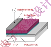
Figure 1: Schematic diagram of organic solar structure.
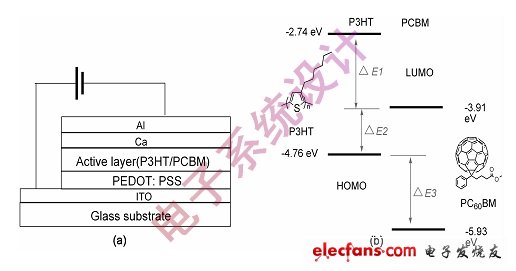
Figure 2: Schematic diagram of the structure of an organic solar cell of a representative donor P3HT and acceptor PCBM and the electronic energy level of the material.
The working principle of an organic solar cell is similar to that of an inorganic material-based solar cell. Sunlight is incident on the active layer from the side of the transparent electrode, and the active layer photovoltaic material absorbs photons to generate excitons (electron-hole pairs); exciton donors Diffusion and migration under the interface of the receptor; the excitons diffused and migrated to the interface undergo charge separation under the action of the electron energy level difference of the donor/acceptor; under the action of the internal potential field of the battery, the separated holes are given along The channels formed by the body are transported to the positive electrode, and the electrons are transported to the negative electrode along the channel formed by the PCBM receptor; the holes and electrons are collected by the positive electrode and the negative electrode, respectively, to form a photovoltaic cell and a photovoltage, thereby generating a photovoltaic effect.
The most important parameters for examining the performance of organic solar cells include: Photovoltaic Convert Efficiency (PCE), Open Circuit Voltage (Voc), Short Circuit Current (Jsc), Fill Factor (FF). . The calculation formula for the conversion efficiency of the battery is:
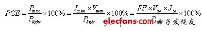
Where Pmax is the maximum output power of the battery, Jmax is the maximum output current of the battery, and Vmax is the maximum output voltage. Plight is the incident light energy.
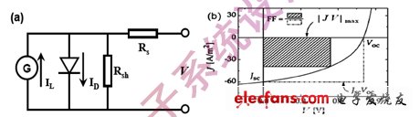
Figure 3: Organic solar cell equivalent circuit and related parameters.
As an alternative energy source, the most important data for examining solar cells is their efficiency in energy utilization, that is, the conversion efficiency of solar cells to incident sunlight. Laboratory-prepared organic solar cells are in part partially metal grid electrodes (small-area battery electrodes are often six-finger structures). Because organic solar cells are inferior to conventional inorganic materials-based batteries in terms of various parameters, they require higher accuracy for testing. Of course, other tests such as simple and fast are also required. In addition to accurate conversion efficiency, accurate measurement data can also obtain Vmax, Jmax, Pmax, and Rsh, Rs and other values. These parameters can accurately examine all aspects of battery performance and provide battery performance improvement for the next step. The basis of the experiment.
The laboratory selected the Agilent B2912A for the organic solar cell performance test source meter, which uses a USB interface. Its minimum measurement resolution of 10fA/100nV is well suited for small current testing of organic solar cells, especially in dark current testing.
Figure 4 shows the connection diagram of the organic solar cell in the B2912A test. The test computer and the source meter are connected by USB cable, which can meet the requirements of data transmission. The test cable and the source meter are directly hard-wired with shielded wires. Interference from other instruments in the room to the test signal.
Figure 5 is a graph of IV in a standard solar and unlit condition for a given solar cell based on P3HT and PCBM for the donor and acceptor B2912A. It can be seen that the source table can meet the high precision requirements of the test data, and can set different delay times to meet the slow feedback requirement of the organic solar cell test signal.
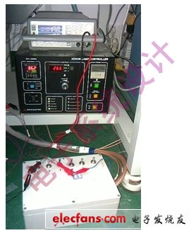
Figure 4: Application of B2912A in organic solar cell testing.
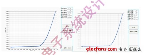
Figure 5: IV curves of the organic solar cells based on P3HT and PCBM with the B2912A test and the IV curve at 1000 W/m2 light intensity and no light.
In the research process of organic solar cells, a large number of cells are subjected to IV testing. Compared with the traditional IV test system, the integrated test system of the B2912A precision measuring unit has the advantages of simple system structure, convenient operation, high precision, high reliability and rapid measurement, which greatly reduces the operating cost and time of solar cell IV performance measurement. Cost, while increasing the flexibility of IV measurement. The B2912A can also test the electrical IV characteristics of organic LEDs and organic MOSFET devices, which can save labor and long-term investment in equipment.
In the long run, the use of solar energy is inevitably a very important way to solve energy and environmental problems. On the other hand, with the continuous development of new technologies, the application of solar cells is bound to become more and more extensive. Among them, organic solar cells will play a very important role because of their unique advantages. In recent years, with a large number of researchers and comparable companies began to research and develop organic solar cells, their development speed is quite rapid, and battery efficiency has also improved significantly. This also puts new demands on organic solar cell testing, and of course brings new opportunities.
As users hands or debris enter the zone 6 inches (15cm) from the infrared sensor on top of the dustbin, the lid will automatically open
Rectangular Sensor Automatic Dustbin
Rectangular Sensor Automatic Dustbin
NINGBO ZIXING ELECTRONIC CO.,LTD. , https://www.zixingautobin.com