The refrigerator delay protector introduced in this example is made of 555 time base integrated circuit and thyristor. The working principle: the refrigerator delay protector consists of power supply circuit, delay control circuit, control execution circuit and working status indication. Circuit composition. The circuit diagram is as shown: 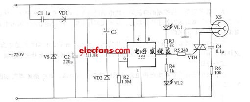
This article refers to the address: http://
Parameter setting: AC 220V voltage is supplied to the IC with a working voltage of +12V (Vcc) after C1 step-down, VD1 rectification, VS regulation and C2 filtering.
Normally, C3 is fully charged, so that the 2 and 6 pins of the IC are low, the 3 pin outputs a high level, the VTH is triggered and turned on, and the AC power is supplied to the refrigerator through the power socket XS. At the same time, VL2 lights up.
When the mains is out of power, the AC voltage on the XS disappears and C3 is rapidly discharged via VD2. When the mains supply resumes power supply, the voltage across C3 cannot be abrupt after power-on, IC 2 and 6 are high (higher than 2 Vcc, /3), 3 pin outputs low level, VTH is still off, XS No AC voltage output, the refrigerator does not work, VLI lights up, indicating that the circuit is in a delayed state. As the +12V voltage is charged to C3 via R2, the potential of the 2 pin and 6 pin of the IC is continuously increased by about 6. 5 min, when the potential of the 2, 6 pin of the IC is lower than Vcc/3, the internal flip-flop is turned over, and the 3-pin output is output. High level, VL2 is lit, VTH is turned on, and the refrigerator is energized.
Component selection:
IC selects NE555 or 561555 time base integrated circuit.
VTH uses TLC336A (3A, 600V) bidirectional thyristor.
VD1 selects I N4007 type silicon rectifier diode; VD2 selects 1 N4148 or 2CK10 type silicon switch diode;
VS selects I N4743 or 2CW110 type (1W, 12~13V) silicon steady voltage diode;
VLl selects Φ5mm yellow light-emitting diode; VL2 selects Φ5mm green light-emitting diode.
R1 to R6 select 1/4W metal film resistors.
C1 and C4 use polyester capacitors or EBB capacitors with a withstand voltage of 400V or higher;
Both C2 and C3 use aluminum electrolytic capacitors with a withstand voltage of 16V.
Piezoelectric Ceramic Actuator Plate,Piezoelectric Bending Ceramic,Piezo Ceramic Diaphragm
NINGBO SANCO ELECTRONICS CO., LTD. , https://www.sancobuzzer.com