With the popularity and development of the Internet, home networking has become the trend of family modernization. Home network, mainly including wired and wireless implementations. Due to the inherent shortcomings of wired networks, troublesome wiring, poor scalability, etc., the application of wireless network technology to home networks has become an unstoppable trend. The market development of wireless networks can be logically divided into two categories: voice-oriented markets and data-oriented markets. In many wireless networks based on data transmission, small, low-cost, low-complexity wireless networks are widely used. ZigBee is one of the representative short-range wireless communication technologies, and its network standard is defined by IEEE 802.15.4. The ZigBee protocol is simpler and more practical than Bluetooth, high-speed PAN (Personal Area Network) or IEEE 802.11x WLAN.
1 Introduction to ZigBee In August 2002, the ZigBee Alliance was established. It consists of Invensys, Japan, Mitsubishi Electric, Motorola, and Philips Semiconductors. The ZigBee standard for IEEE802.1 5.4 was approved in May 2003; ZigBee 2006 was launched, which is relatively complete; at the end of 2007, ZigBee PRO was launched. The underlying technology of ZigBee is based on IEEE 802.15.4. The physical layer and the MAC layer directly reference the IEEE 802.15.4 standard. The ZigBee Alliance is responsible for the development of the network layer and application layer, as well as the development of its security protocols and marketing. IEEE 802.15.4 defines two physical layer standards, the 2.4 GHz physical layer and the 868/915 MHz physical layer. Both physical layers are based on DSSS direct sequence spread spectrum technology, using the same physical layer packet format. ZigBee has 16 channels in the 2.4 GHz band and can provide 250 Kb/s transmission rate with 0-QPSK modulation; 915 MHz and 868 MHz are the ISM bands in Europe and the United States, respectively. The introduction of these two bands avoids Mutual interference of various wireless communication devices near 2.4 GHz.
2 Home Network Topology Selection The ZigBee standard has three network topologies: star, mesh, and tree. The actual situation of the smart home system is as follows: 1) The sensor node is powered by the battery, and the home gateway is powered by the power supply, so the workload of the sensor node should be minimized to save the power of the sensor node; 2) the main access in the smart home It is a sensor and a switch. The amount of data in the network is not large. It is not necessary to use a complex network topology to ensure data communication. 3) The design of the smart home control network does not require a large coverage. According to the ZigBee standard, the maximum transmission in the open environment With a distance of 100 m, the indoor environment can generally reach a coverage distance of more than 30 meters, which is enough for most smart home systems. The star topology can meet the requirements, and the cost is low, the implementation is simple, the connection is easy, the expansion and management are easy, and the functions such as routing and addressing are not involved. Therefore, the design selects the star topology.
3 Network node design Network node consists of single-chip microcomputer, wireless transmission module, data acquisition and control circuit, as shown in Figure 1. Among them, the single-chip microcomputer selects low-power ATMEGA128L, the wireless module selects CC2-420 type RF transceiver, and the two are connected through SPI interface. ATMEGAl28L is a high-end 8-bit microprocessor with high performance, low power consumption, 128 Kbytes of programmable FLASH, 4 Kbytes of SRAM, and a simplified and efficient RISC instruction set.
This article refers to the address: http://

The CC2420 is an RF transceiver that complies with the 2.4 GHz IEEE 802.15.4 standard. This device is an RF device for ZigBee products. Based on Chipeon's Smalt RF 03 technology, it is fabricated in a 0.18μm CMOS process with minimal external components, stable performance and low power consumption. The CC2420's selectivity and sensitivity index exceeds the requirements of the IEEE 802.15.4 standard to ensure the effectiveness and reliability of short-range communications.
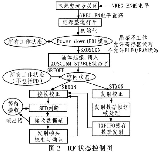
The CC2420 requires very few external components. The peripheral circuits include the crystal clock circuit, the RF input/output matching circuit, and the microcontroller interface circuit. The CC2420 sets the operating mode of the chip through the 4-wire SPI bus (SI, S0, SCLK, CSn), and implements functions such as reading/writing buffer data and reading/writing status registers. The transmit/receive buffer can be set by controlling the state of the FIF0 and FIFOP pin interfaces. Note: Address and data transfers on the SPI bus interface are mostly MSB-first. The CC2420 has 33 16-bit status setting registers. In the read/write cycle of each register, there are 24 bits of data on the SI bus, which are: 1-bit RAM/register select bits (0: register, 1: RAM). , 1-bit read/write control bit (0: write, 1: read), 6-bit address select bit, 16-bit data bit. CSn must always be held low during data transfer. Figure 2 is an RF state control diagram. In addition, the channel estimation can be controlled by setting the CCA pin status, and the clock/timing information input can be controlled by setting the SFD pin status. These interfaces must be connected to the appropriate pins of the microprocessor to control and manage the RF functions of the system.
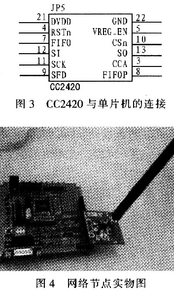
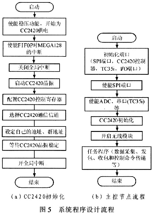
The connection between CC2420 and MCU is shown in Figure 3. The number is the corresponding pin of ATMEGAl28. The network node transmits the command and status through the CC2420 wireless module and controls the switch of the electrical device through the relay. The system node is shown in Figure 4.
The network node transmits the command and status through the CC2420 wireless module and controls the switch of the electrical device through the relay. The system selects a node as the master node of the star network. The node connects to the short message module, communicates directly with the user, and transmits user commands to other nodes while sending node status and alarm information to the user. The SMS module uses Siemens' TC35i. The Siemens TC35i module is an industrial-grade GSM module that supports short messages in English and Chinese.
The interface between the short message technology based on the GSM network and the processor is actually implemented by a series of AT commands. When the short message module receives the short message sent by the network, the short message module can send the indication information to the single chip through the serial port, and the user can query and control the state of the electrical device. Text mode and PDU mode of short messages Currently, text mode and PDU mode are commonly used to send short messages. Using text mode to send and receive text messages is simple and easy to implement, but the biggest disadvantage is that you can't send and receive Chinese text messages. The PDU mode not only supports Chinese text messages, but also can send English text messages.
PDU mode can send and receive text messages using three types of codes: 7 bit, 8 bit and UCS2 code. 7 bit encoding is used to send normal ASCII characters, 8 bit encoding is usually used to send data messages, and UCS2 encoding is used to send Unicode characters. The general PDU code consists of thirteen items, which include: short message center address length; short message center number type; short message center number; file header byte; information type; called number length; called number type; Number; protocol identification; data coding scheme; validity period; user data length; user data.
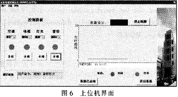
4 System software design system selects a node as the master node of the star network. The node connects to the short message module and communicates directly with the user. It transmits user commands to other nodes and sends node status and alarm information to the user. Other nodes except the SMS module and tasks are basically the same as the main node process. Each node has its own fixed address and there is no interference between them. Figure 5 shows the program flow of the system design.
Using VB to design the host computer interface, the user can enter the control system through the PC, which can realize the control of the electric appliance and directly observe the required environmental parameters. Figure 6 shows the host computer interface.
5 Conclusion Through the test, the outdoor communication distance of the node is up to 200 m, and the indoor is 40 m. The power consumption of the node is low. It is powered by two dry batteries and can be used for 3 to 6 months. ZigBee technology complements the gap in the low-cost, low-power, near-range and low-rate wireless communications markets. The system uses a ZigBee technology to build a wireless home control network that eliminates the need for any changes to the indoor wires and requires no additional cabling. The extension can increase the control capacity, and the expansion is convenient and easy.
Lifepo4 Lithium Battery cells are gaining more popularity among E-bike users for its features of long cycle life, light weight, safe performance, and deep depth of discharge.
Lfp Battery,Electric Bike Cell,A Bike Electric
FORZATEC CO., LIMITED , http://www.forzatec.com