This paper presents a multi-channel lithium battery charge and discharge testing system, utilizing the STM32F429 as the central controller. The system is equipped with dual-range current sensing, charge and discharge control, temperature and voltage monitoring circuits, and is designed to test and protect series-connected power lithium battery packs. Through the host computer software, users can monitor the charging and discharging process of multiple lithium battery packs in real time and analyze the collected data effectively.
**1. System Hardware Design**
The system employs the high-performance, low-cost STM32F429 microcontroller from STMicroelectronics as its core. It communicates with various modules—current, temperature, and voltage detection—via SPI and SMBus interfaces. The main control chip also manages the opening and closing of the charge and discharge circuit through general-purpose I/O pins, enabling essential protection functions. Collected data is transmitted to the host computer via a USB module, allowing real-time monitoring and analysis. The system consists of 8 independent channels, each capable of monitoring 1 to 8 lithium batteries. Additionally, channels can be combined to monitor up to 16 batteries in series, providing flexible and scalable testing capabilities.
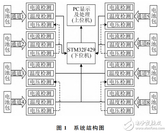
The hardware design includes key components such as the lithium battery voltage detection module, temperature detection module, current detection module, and charge/discharge protection module.
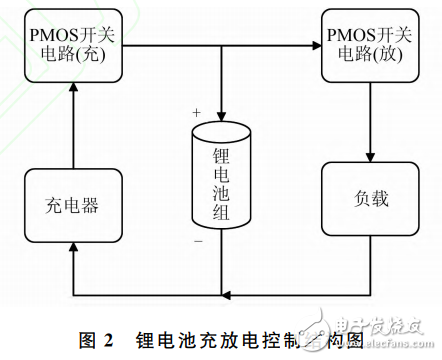
**1.1 Current Detection and Charge/Discharge Control Hardware Design**
Current is a critical parameter during the charge and discharge process of lithium battery packs. It directly indicates whether overcurrent conditions occur and is essential for estimating total charge using integration methods. Therefore, accurate current detection is vital for reliable charge and discharge data processing.
To ensure versatility across different lithium battery types and capacities, the system uses a dual-range current sensing approach. This allows precise measurement at both low and high current levels, enhancing the system's overall performance. Each channel incorporates a closed-loop Hall current sensor (MMI-200B), known for its wide dynamic range, high accuracy, fast response, and isolation capability. The primary current Ip flows through the sensor’s hole, and the secondary output current Io is related to Ip by the equation:
n × Ia = K × Io. (1)
Where K is the proportional coefficient (K=1000 for MMI-200B), and n is the number of turns in the primary coil (n=2 in this system).
To measure the current accurately under varying conditions, the system controls the switching of a relay (G6K-2P) via the STM32’s IO pins. This selects between different sampling resistors, ensuring precision. The selected signal is then converted by the ADS1247, a high-precision 24-bit ADC with two differential inputs. The STM32 reads the ADC values through the SPI bus and calculates the charge and discharge current for each channel.
Packages For Fiber Optic Communication,Optical Housings,Optical Communication Component,Optical Communication Fine Tube
Shaanxi Xinlong Metal Electro-mechanical Co., Ltd. , https://www.cnxlalloys.com