Abstract: This paper presents the design of a beamforming array antenna tailored for automotive backward collision avoidance radar systems. A cross-fed microstrip array antenna is developed to achieve a low sidelobe radiation pattern in the elevation plane. The excitation amplitude and phase of the horizontal beamforming pattern are optimized using the Particle Swarm Optimization (PSO) algorithm. A power division network is then designed to realize the desired beam pattern. Finally, the shaped array antenna is integrated with the feeding network to complete the beamforming array antenna design. This research provides valuable insights for the application of beamforming techniques in vehicle anti-collision radar systems.
1. Introduction
Thanks to the advancement of artificial intelligence software, particularly deep learning, and more reliable computer and sensor technologies, cars are expected to gain human-like capabilities in unpredictable environments in the next few decades. Autonomous driving systems will gradually replace traditional manually driven vehicles. In this transition, millimeter-wave anti-collision radars serve as the "eyes" of driverless cars, collecting crucial information such as speed, distance, and position of surrounding objects. As a result, research on millimeter-wave anti-collision radar has become a focal point for automotive electronics manufacturers in recent years.
2. Introduction to Car Anti-Collision Radar
Anti-collision radars used in automobiles typically operate in two frequency bands: 24 GHz–24.25 GHz and 76 GHz–81 GHz. Radars operating in the 24 GHz band are generally installed at the rear of the vehicle for functions such as blind spot detection (BSD), lane change assistance (LCA), and reverse parking warning (RCTA). On the other hand, millimeter-wave anti-collision radars in the 76 GHz–81 GHz band are usually positioned at the front of the vehicle for adaptive cruise control (ACC) and emergency braking (AEB). The functional coverage areas of these radars are illustrated in Figure 1.

Figure 1 Schematic diagram of the anti-collision radar beam coverage area
The beamforming array antenna described in this paper operates at 77 GHz–79 GHz as part of a rear-mounted millimeter-wave collision radar system, supporting BSD, LCA, and RCTA functions. While 24 GHz radars can also perform similar tasks, 77 GHz radars offer higher speed detection accuracy, longer range, better resolution, and a smaller size, making them easier to integrate into the rear bumper or taillights of a vehicle.
3. Design of Beam Shaping Array Antenna
3.1 Series-Fed Microstrip Patch Array Antenna
Microstrip antennas are widely used due to their low profile, lightweight, ease of fabrication, low cost, and compatibility with microwave circuits. A series-fed microstrip patch array can produce high gain and low sidelobe patterns, making it suitable for use in millimeter-wave anti-collision radar applications.
3.1.1 Theoretical Analysis
A microstrip patch antenna can be considered an open-circuit resonator with no change in the lateral direction [2]. Radiation occurs through the open gap on either side of the patch along its length, as shown in Figure 2.
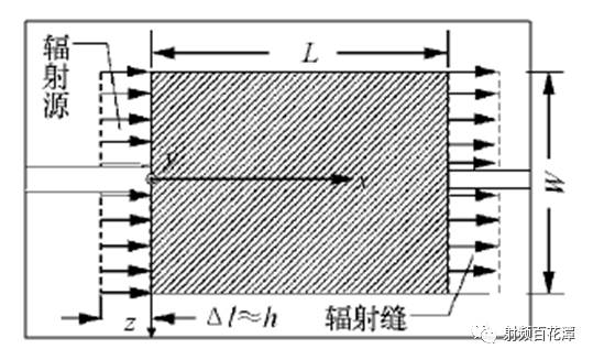
Figure 2 Rectangular microstrip patch antenna
By connecting the patches in series through a microstrip transmission line, a standing wave array is formed. The spacing between the patches is shown in Figure 3.
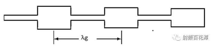
Figure 3 Schematic diagram of the structure of the series-fed microstrip patch line array
In a series-fed microstrip patch array, the width of each patch is proportional to its equivalent admittance, which is directly related to the excitation power. By adjusting the width of each patch, the excitation power can be controlled, achieving a tapered distribution that meets the low sidelobe requirements for the elevation plane of the anti-collision radar antenna.
3.1.2 Simulation Design
Based on the required gain and beamwidth, the series-fed microstrip patch line array consists of 10 elements, with a sidelobe level below -20 dB. A RO3003 dielectric substrate with a thickness of 5 mil was optimized through theoretical analysis and simulation software. The simulation model is shown in Figure 4.
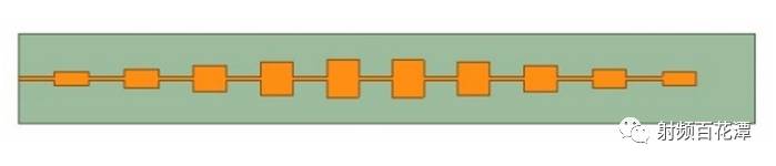
Figure 4 Antenna simulation model
The pitch surface gain pattern is shown in Figure 5.
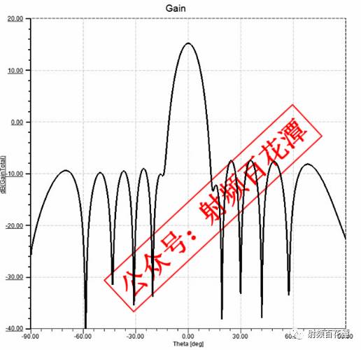
Figure 5 Pitch surface gain pattern
The line array achieves a gain of 15.1 dBi with a sidelobe level of -22.6 dB. The line array model from Figure 4 is arranged in 6 rows to form a planar array, as shown in Figure 6.
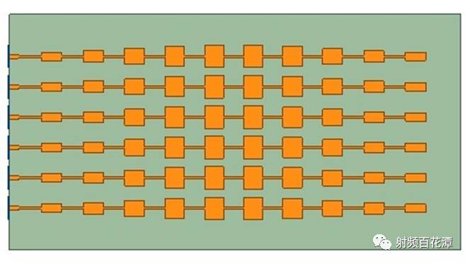
Figure 6 Area array simulation model
This planar array is used to implement the beamforming of the horizontal plane pattern.
3.2 PSO Algorithm for Excitation Amplitude and Phase Optimization
The basic concept of particle swarm optimization (PSO) is inspired by the behavior of bird flocks [3]. Like genetic algorithms, PSO is a random search method, but it does not involve complex processes like selection, crossover, or mutation. Instead, particles update their positions and velocities by tracking the best solution found by themselves (Pbest) and the best solution found by the entire group (Gbest), gradually approaching the optimal solution. The flowchart of the PSO algorithm is shown in Figure 7.
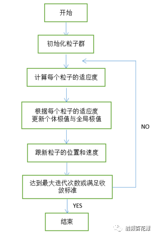
Figure 7 Algorithm optimization flow chart
The target pattern for beamforming is extracted from the power diagram of the anti-collision radar. The excitation phase of the array antenna in Figure 6 is optimized using the PSO algorithm to shape the target pattern. In HFSS simulation software, the amplitude and phase values obtained from the PSO algorithm are input, resulting in the simulated beam pattern shown in Figure 8.
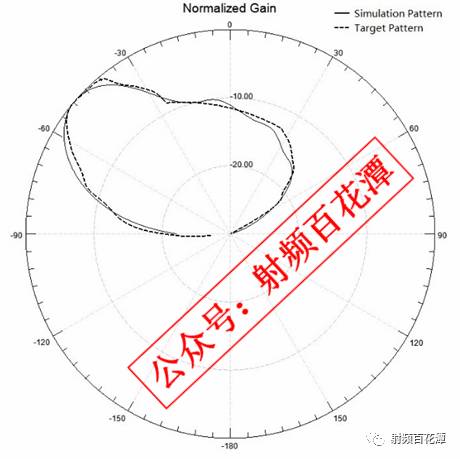
Figure 8 Beam shaping pattern
It can be seen from Figure 8 that the simulation results align well with the target pattern, confirming the reliability of the results obtained from the PSO algorithm.
3.3 Design of Power Division Network
Section 3.2 determines the amplitude and phase values for each line array excitation. However, the simulation pattern in Figure 8 is ideal. In practice, a 1:6 power division network is needed. Commonly used power splitters include Wilkinson splitters and T-section power splitters. While Wilkinson splitters are limited in forming and feeding networks, they suffer from high losses and large size, which is not ideal for miniaturization. In contrast, the series-fed power distribution network offers low loss and a compact footprint, making it more suitable for implementing the beam-phase excitation from Section 3.2.
3.3.1 Theoretical Analysis
The series-feed network uses impedance transformation segments to achieve the beamforming excitation amplitude, while the excitation phase is adjusted by varying the length of the output feeder. The equivalent circuit of the series feed network is shown in Figure 9.
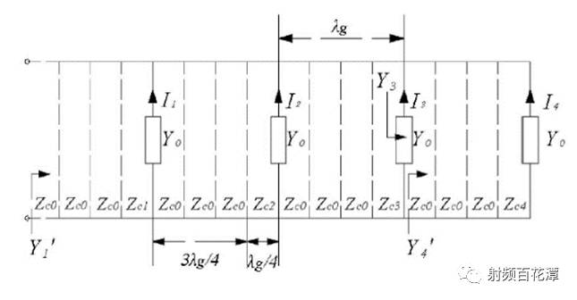
Figure 9 Series feed network equivalent circuit
In the figure, Yo represents the equivalent admittance of the serial feed line array connected to the power division network. Zci is the characteristic impedance of each impedance transformation segment, and Zco is the characteristic impedance of the feeder line. The relationship between the excitation current and impedance at the output port of the series feed network is given by [4].

The excitation current Ii for each port is optimized in Section 3.2, and the characteristic impedance Zco of the transmission line is known. From this, the characteristic impedance corresponding to each impedance transformation segment can be calculated, allowing the width of the microstrip line to be determined based on the characteristic impedance.
3.3.2 Simulation Design
The power division network simulation model is shown in Figure 10.
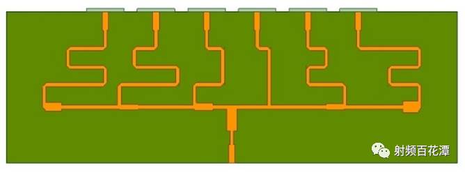
Figure 10 Power network simulation model
The simulated amplitude and phase data are shown in Table 1.

Table 1 Simulation and PSO Optimization of Amplitude and Phase Data
As shown in Table 1, the power split network effectively realizes the amplitude and phase values optimized by the PSO algorithm.
3.4 Overall Simulation Results
Figure 10 shows a sub-network connected to the area array in Figure 6, forming a complete simulation model as shown in Figure 11.

Figure 11 Overall simulation model
The simulation of the azimuth plane pattern compared to the target pattern is shown in Figure 12.
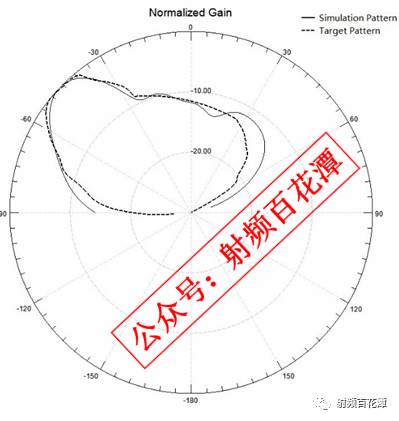
Figure 12 Simulation vs. Target Pattern
From Figure 12, it is clear that the simulation pattern agrees well with the target pattern within the range of -60° to +36°, with slight deviations outside this range due to antenna coupling effects. These differences in amplitude and phase at angles away from the main beam do not significantly affect the performance of the radar. Overall, the simulation pattern meets the three key functions of the backward anti-collision radar: BSD, LCA, and RCTA.
4. Conclusion
This paper presents the design of a beamforming array antenna for vehicle backward collision avoidance radar operating in the 77 GHz–79 GHz frequency band. First, a cross-fed microstrip array is designed to achieve a high gain and low sidelobe pattern in the elevation plane, reaching a sidelobe level of -22.6 dB. Then, six line arrays are equally arranged to form a planar array, and the PSO algorithm is used to optimize the excitation amplitude and phase of the azimuth-shaped beam. A 1:6 cross-fed power distribution network is employed to realize the optimized amplitude and phase values. Finally, the network is connected to the planar array to complete the beamforming array antenna design. The simulation results show good agreement with the target pattern, demonstrating the practical value of this design for 77 GHz automotive anti-collision radar systems.
Litz Wire Typical applications are: high frequency inductor, transformer, frequency converter, fuel cell, the horse, communication and IT equipment, ultrasound equipment, sonar equipment, televisions, radios, induction heating, etc.In 1911, New England became the first commercial manufacturer in the United States to produce the Leeds line.Since then, New England has remained the world leader in providing high-performance Leeds line products and solutions to customers around the world.It is also transliterated as the "litz line".

Litz Wire,Copper Litz Wire,Copper Transformer Litz Wire,High Temperature Litz Wire
YANGZHOU POSITIONING TECH CO., LTD. , https://www.yzpst.com