1 Introduction
According to JTJ 026. 1—1999 Highway Tunnel Ventilation Lighting Design Specification, tunnels with a length greater than 100m shall be provided with illumination [1]. Due to the backward manufacturing process of the light source, the poor dimming performance and the backwardness of the control methods, in order to ensure the safety in various situations, the design of the tunnel lighting system is considered to have the largest brightness requirement, and there is a large amount of redundancy, resulting in excessive The lighting is serious. The brightness outside the hole is calculated according to the maximum brightness at noon in the summer, and the actual brightness outside the hole changes continuously with the weather, season and time. The maintenance factor of 0.7 is taken according to the literature [1], as the brightness of the light source is attenuated with the increase of the use time and the brightness of the luminaire is reduced. In addition to this, certain design redundancy [2] is also considered, resulting in excessive illumination. In the literature [1], the inlet section, the transition section, the middle section and the outlet section are valued according to the step type. When the lamp is arranged, whether it is symmetrically arranged, staggered, arranged in the middle or in a sub-loop arrangement, the power of the single lamp is large, so that the lamp room is The distance is also large, which will result in uneven illumination distribution. Lamps such as fluorescent lamps, high-pressure sodium lamps, and metal halide lamps cannot be dimmed or adjusted in a small range, and the dimming is complicated and costly. Therefore, current tunnel lighting systems generally cannot be dimmed or sub-circulated with level dimming [3]. LED lighting has high efficiency, energy saving, environmental protection, long life, short response time, convenient dimming [4], and has broad prospects in tunnel lighting.
2 Comparison of domestic standards and CIE standards
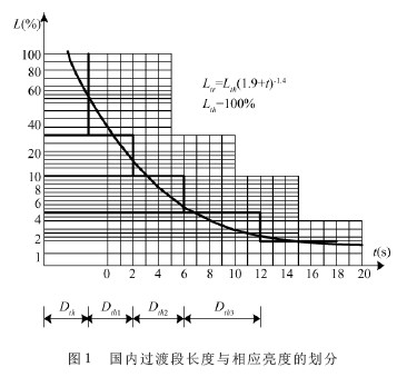
In highway tunnel lighting, the illuminated section between the inlet section and the base section is referred to as a transition section. Its task is to solve the incompatibility caused by the drastic changes of the high-intensity Lth of the entrance section to the low-intensity Lin of the basic section, so that it can have sufficient time transition and achieve this transition with gradual enhanced illumination [5]. The CIE adaptation curve Ltr = Lth (1. 9 + t) - 1. 4 is used in the design specification of road tunnel ventilation lighting JTJ026. 1—1999 as the basis for the division of brightness and length of the transition section. The brightness ratios of the three transitional illumination segments TR1, TR2, and TR3 are divided by 3:1, as shown in Figure 1.
Ltr1 = 0. 3Lth , Ltr2 = 0. 1Lth , Ltr3 = 0. 035Lth , the brightness changes greatly, especially for the first time as much as 0. 7Lth, if the hole outside the brightness L20 (S) = 5000cd / m2, driving speed v = 80km / h, brightness reduction factor k = 0. 035, Lth = 5000 × 0. 035 = 175cd / m2 and the transition point of the transition 1 segment, the brightness changes as much as 122. 5cd / m2, not conducive to the eyes Adjustment and adaptation are not conducive to driving safety.
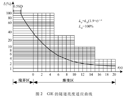
According to the literature [2], the total length of the three transitions is 72 + 89 + 133 = 294m, and the total adaptation time is 13.23s. Although the "Code for Ventilation Design of Road Tunnels JTJ026. 1-1999" refers to "CIE88-1990. GUIDE FOR THE LIGHTING OF ROAD TUNNELS AND UNDERPASSES" [6], the division of each section in the tunnel is different. The CIE standard divides the transition process into three parts. The brightness is maintained at the first half of the parking distance, and the driver is allowed to adapt to the tunnel. The second half of the parking distance begins to decrease the brightness, first linearly decreasing to 0. 4Lth, then entering the gradient. In the area, the brightness is gradually reduced by the adaptation curve Lth (1. 9 + t) - 1. 4 until it is equal to Lin, as shown in Figure 2.
All of the above are ideal transition processes. Due to the limitations of the previous technical conditions, the luminaires cannot be adjusted as needed according to the brightness requirements of the adaptive curve. Instead, the CIE adaptation curve is divided into three segments [1], and the luminance values ​​are respectively 0. 3Lth , 0. 1Lth , 0. 035Lth , the adaptation distance is Dtr1 = Dth /3 + v /1. 8; Dtr2 = 2v /1. 8; Dtr3 = 3v /1. 8. The transition of the domestic standard, including by Lth to 0. 4Lth and by 0. 4Lth
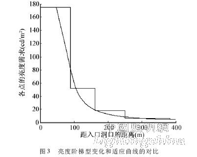
Go to Lin two adaptation processes. In fact, the adaptation curve is not fixed, and the brightness is changed in real time with the outside of the hole. The adaptation distance is also calculated from the adaptation time and the vehicle speed. In order to ensure the safety of driving, the specification considers the maximum outside brightness of the hole, so that when the brightness outside the hole becomes small, the brightness of the transition section is much larger than the actual requirement, and the length of the transition section is larger than the actual demand due to the fixed length of the transition section. More lighting fixtures were turned on, causing waste of electrical energy. At the same time, due to the segmentation adjustment, the brightness shows a step-type change, and it is a jump of 4 times of large brightness, which is not conducive to the comfort and safety of driving. A comparison of the brightness step change and the adaptation curve is shown in Figure 3.