This paper introduces the related module design of USB HOST function based on single chip microcomputer and USB HOST interface chip in the vehicle drive recorder. This module can realize the rapid transmission of large amount of data from the single chip to the USB flash drive in the vehicle drive recorder.
This article refers to the address: http://
Overall design of the USB HOST related module
The USB HOST related module in the car tachograph consists of a single chip microcomputer, USB HOST interface, FLASH, ferroelectric memory (FRAM), real-time clock and power management. The functional block diagram is shown in Figure 1. When the car tachograph is working, the MCU picks up various information about the driving state of the car through the front end interface circuit, including the vehicle speed, engine speed and various vehicle switching signals. The car tachograph uses the real-time clock as a reference to store vehicle information in FRAM and FLASH by category. When the vehicle record status information needs to be obtained from the car tachograph, the user inserts the USB flash drive, and the MCU automatically recognizes the USB flash drive and loads the driver. When the device enumeration and the Bulk_Only transfer protocol are completed, the MCU can record the status recorded in the car drive recorder. The information is transferred to the USB flash drive as a file. This article focuses on the hardware design of the power module, USB HOST module, and data storage module.
Considering the complex working conditions of the car and the cost performance of the recorder, the MCU is at least an industrial grade product. Because of the USB HOST structure, the FLASH and RAM are large enough, so that the system resources are sufficient. In addition, considering the cost and development cycle, the MCU selects the 51 series more favorable. Combining the above factors, the MCU selects the AT89C51RD2 and expands the RAM; currently there are more USB device chips on the market, and the HOST is less. There are two points to consider when choosing a USB HOST interface chip: First, it must be easier to connect with 51 MCUs on the hardware. Second, the software development difficulty cannot be too large, so choose SL811HST. For the data storage body, the storage time must be 15 years effective, and the storage capacity is at least 360 hours of valid data. The number of ordinary data FLASH erasing is 1 million times, which cannot meet the requirements of frequent erasing data in the recorder, and the ferroelectric The number of erasing is unlimited, but the price of large-capacity FRAM is very high. Combining these two points, the storage unit is combined with small-capacity FRAM and FLASH, which not only meets the requirements of the recorder but also has a relatively low cost.
Power module hardware design
The most fundamental cause of electromagnetic interference in automotive electronics is the di/dt generated during its operation. The power module design is to work normally under these interference sources, and its hardware circuit is shown in Figure 2.
At the power input, the diode VD1 (IN4007) is used to prevent reverse connection, so that the electronic device will not be damaged even if the power supply is reversed; VD2 (A36A) is a transient suppression diode that can absorb high voltage pulse voltage. To prevent damage to electronic equipment caused by high-voltage pulses generated by high-power devices; L1 and L2 are low-inductance magnetic strips, which can effectively reduce the energy of interference components, and can improve power supply performance; F1 and F2 are self-reset The level tube prevents damage to other devices caused by short-circuiting of the power supply when the device inside the electronic device is damaged. The three-terminal regulator 7812 (N2) provides 12V voltage to meet the needs of the front-end input interface pickup circuit, while providing input to the three-terminal regulator 7808 (N1), N1 provides 8V voltage, to meet the mileage output and speed output needs, the switch is stable The LM2576 (N3) provides a 5V output with a maximum output current of 3A to meet the needs of the recorder with a printer. The WRD24B05 (N4) is a DC-DC converter that isolates the power supply of automotive and electronic equipment to make the power supply stable and reliable. The forward voltage regulator SPX1117 (N5) provides 3.3V for the SL811HST and the bank. The N85 front-end transistor 8550 controls the input of the N6. The N6 supplies power to the IC card and requires power control.
USB HOST module hardware design
In the USB HOST module of the vehicle driving recorder, the single-chip microcomputer adopts AT89C51RD2, and the USB HOST interface chip adopts SL811HST. The hardware circuit of the module is shown in Figure 3. The SL811HST provides the parallel port bus data protocol and control lines CS, RD, WR, INTRQ and A0. The SL811HST and AT89C51RD2 can be connected by using the read/write signal lines RD and WR of the MCU and the control lines A0 and INT1. Among them, 8 data lines are exchanged with the AT89C51RD2 under the control of the control line. USB HOST includes USB device enumeration protocol, Bulk_Only transfer protocol and FAT file structure. The RAM resources of AT89C51RD2 are not enough. Therefore, the system expands 32Kb SRAM, which occupies a low 32Kb address. In order to ensure the reliability of the operation of the SL811HST, the logic circuit is extended with HC00, so the SL811HST occupies two addresses of 0x8000 and 0x8001. In addition, the electrical characteristics of the USB bus require that 22 to 44 Ω resistors must be connected in series before the USB transceiver, and the position of the pull-up resistor and pull-down resistor must be configured according to the transmission speed of the USB device (full speed or low speed).
When CS, RD are active, if A0 is high, this is reading the current address or register data. If A0 is low, the current address or register address is read. When CS, WR are active, if A0 is high, this is to write the current address or register data. If A0 is low, write the current address or register address.
The process of USB HOST identification device is as follows: When the SL811HST is connected to the USB device, an interrupt is generated. After receiving the interrupt, the AT89C51RD2 enters the enumeration process. There is still work to do from the time the USB device is plugged into the interface until the client driver can use the device. This section can be called the device identification process, also known as the enumeration process. The enumeration process is a must-have process before all USB devices are used. Before using the USB HOST terminal, you need to know whether it is a low-speed device or a full-speed device. You need to know some features and capabilities of this device in order to load the corresponding driver. After the USB HOST is configured with the USB device, the Bulk_Only Mass Storage device is identified by the information provided by the descriptor, and then the Bulk_Only transmission mode is entered. In this mode, all data between the USB and the device is transmitted through Bulk_In and Bulk_Out. No data is transmitted through the control endpoint. In this mode of transmission, there are three data types that are transmitted between the USB and the device, CBW, CSW, and normal data. CBW (Command Block Wrapper) is a command sent from the USB HOST to the device. The format of the command follows the command block specified by bInterfaceSubClass in the interface, here is the SCSI transfer command set. The USB device needs to extract the SCSI command from the CBW, execute the corresponding command, and issue the current command execution status CSW (Command Status Wrapper) to the HOST after completion. The HOST determines whether to continue to transmit the next CBW or data according to the CSW. USB HOST requires the command executed by the USB device to send data, then the specific data needs to be transmitted at this time, and the CSW is sent after the transfer is completed, so that the USB HOST performs the next operation.
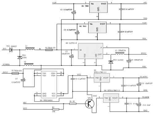
Figure 2 Power module schematic
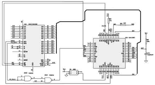
Figure 3 USB HOST module schematic
Storage module hardware design
Combining ordinary FLASH and FRAM to store data, it not only meets the requirements of data storage and erasing times, but also has relatively low cost. The hardware circuit of the data storage module is shown in Figure 4.
The FRAM chip FM24CL16 is connected to the AT89C51RD2 via an I2C interface. The I2C bus is connected to any device on the bus through two wires, serial data (SDA) and serial clock (SCL). Each device has a unique address. And can be used as a transmitter or receiver. In addition, the device can also be regarded as a master or slave when performing data transfer. I2C is a multi-master bus. Both SDA and SCL are dual-wire. The output stage of the device connected to the bus must be open-drain or open-collector. Both are connected to a positive supply voltage through a current source or pull-up resistor. Both lines are high when the bus is idle. The FLASH chip AT45DB041 is connected to the AT89C51RD2 through the SPI interface. The SPI is a full-duplex serial interface that uses a three-wire synchronous data transmission format. In a certain data transmission process, only one host and one slave can communicate on the interface. In one transmission, the master always sends one byte of data to the slave, and the slave always sends one byte of data to the switchboard.
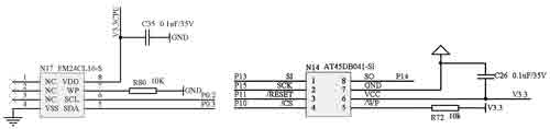
Figure 4 Storage Module Principles
summary
This design realizes the USB HOST function of the car drive recorder, enabling the car tachograph and the USB flash drive to exchange a large amount of data. Based on the design of the product in the process of inspection, certification and use, USB HOST technology performance meets product design requirements and technical requirements, which is convenient for users to quickly collect large amounts of data.
Epoxy resin seal type NTC Temperature Sensor with the properties of good stability, fast response, temperature resistance, convenient to use, has been already applied to air conditioner, automotive, electrical appliance and induction cooker. Temperature range is from -30°C to 105°C.
Epoxy Resin Seal Sensor
Epoxy Resin Seal Sensor,Stability Sensor,Greenhouse Sensors,Bus Sensor
Feyvan Electronics Technology Co., Ltd. , http://www.fv-cable-assembly.com