1. Introduction ï€
This article refers to the address: http://
Reasonable matching of the damping characteristics of the automotive suspension system plays a crucial role in improving ride comfort and handling stability. At present, foreign automobile manufacturers generally adopt a series of dampers or mechanical adjustable dampers with different damping characteristics, and combine the subjective and objective evaluation methods to experimentally match the suspension damping parameters [1~2], domestic automobile enterprises. Foreign technical support is still needed. However, the matching method can only achieve the compression damping and the restoration damping linkage adjustment (or the damping discrete adjustment), and it is difficult to achieve the optimal and automatic matching of the suspension damping parameters. Therefore, the automatic matching method with independent intellectual property rights and innovative features is studied. It has important practical significance to improve the development capability of China's automobile suspension.
Damping adjustable magnetorheological damper has the unparalleled advantages of traditional passive hydraulic damper [3], which is used to replace the manual adjustment of mechanical adjustable damper to study the optimal and automatic matching of vehicle suspension damping parameters. It is an ideal choice. The theoretical method and key implementation technology for automatic matching of vehicle suspension damping parameters involves a series of problems that need to be solved. It is one of the key technologies to develop a controllable state sensitive current source that functions to identify the operating state of the vehicle damper (recovery and compression conditions). For a specific automotive magnetorheological damper, the independent adjustment of the damper compression and the recovery damping parameters is achieved by adjusting the excitation current for a given excitation condition, so that the steering stability and ride comfort of the vehicle are optimized, and the damper is obtained. The damping characteristics under this excitation lay a solid technical foundation for the successful development of an automatic matching device for vehicle suspension damping parameters.
2, system composition and hardware and software design
2.1 System working principle and composition
The working principle of the system is: at a certain moment, by analyzing the data of the sensors fixed on the damper piston rod and the working chamber, it is judged that the damper is in a stretched or compressed state compared with the previous moment, according to Different states dynamically change the current through the damper excitation coil, causing the internal magnetic field to change, thereby achieving the purpose of changing its damping force.
When working, the main vibration frequency of the damper in the vertical direction is about a few hertz, and the vibration amplitude is about several hundred millimeters. It is judged that it is stretched or compressed at a certain moment compared with the previous moment, and it is judged by ultrasonic waves. A more economical method [4]; but due to the delay of ultrasonic ranging, it is difficult to accurately measure the transit time, domestic and foreign scholars have made a lot of efforts in this regard [5-7]; It is not necessary to know the exact vibration displacement data of the damper. Therefore, the measured time value comparison method is used to judge the tension or compression state of the damper.
The system composition is shown in Figure 1. The ultrasonic part senses the motion state of the damper. The digital signal processor TMS320LF2407A recognizes the motion state of the damper and then outputs a control signal to the current driver.
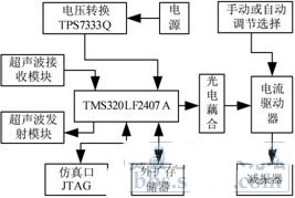
Fig.1 Block diagram of the magneto-rheological fluid damper operating state sensitive current source system
2.2 System main hardware design
2.2.1 Ultrasonic transmitter module
Ultrasonic transmitting circuit shown in Figure 2, because the measuring distance is small, the system does not use transformer boost to drive the ultrasonic transducer, the controller directly generates 40KHz ultrasonic pulse signal, driving the switch tube 3904, in order to provide the transmitter head The large drive current uses two non-gate parallel connections; in order to effectively contain the residual vibration of the ultrasonic transmitter, a non-gate is used to provide a phase shift signal of 180 degrees on one side of the driver and an in-phase signal on the other side. Drive; the supply voltage is 5V; the capacitors C2 and C3 block the DC path and convert the DC voltage into an equal-amplitude alternating voltage, so that the transmitter can work reliably and stably for a long time.
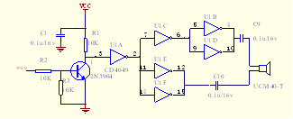
Figure 2 Ultrasonic Transmitting Circuit
2.2.2 Ultrasonic receiver module
The ultrasonic receiving module adopts CX20106A chip, which is composed of preamplifier, limiting amplifier, wideband filtering, detection, waveform shaping, hysteresis comparator and other circuits; 1 pin is signal input, 2 pin is preamplifier frequency characteristic and Gain setting terminal, 3 pin connected to the peak detection capacitor, 5 pin resistor to set the center frequency of the bandpass filter, 6 pin to the integral capacitor, 7 pin output, when the signal is detected, output a low level, due to the DSP The level (3.3 volts high) matches, using R3, R4 partial pressure.
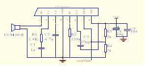
Figure 3 ultrasonic receiving circuit
2.2.3 Main controller and peripheral circuits
The controller adopts TI's TMS320LF2407A digital signal processor, and has up to 32K words of Flash program memory on the chip, so that the system does not need to expand the program memory; the T1PWM compare output 40KHz square wave drive ultrasonic transducer, CAPTURE4 pairs receive The signal is detected by the interrupt caused by the signal. The timer T3 counts the propagation time of the ultrasonic wave. To facilitate debugging, the system also expands a 64K word data memory IC61LV6416. After the debugging is completed, the program is written into the on-chip flash, and the system is Can run independently from the development environment.
The power circuit uses LM2596 to convert 12V to +5V, its output current is up to 3A, the average working efficiency can reach more than 80%, and then converted from TPS7333Q to 3.3V for the main control chip TMS320LF2407A and its peripheral circuits, which can fully satisfy the system. Power supply requirements.
JTAG interface, mainly used for internal chip testing and programming, simulation, debugging, etc.; TMS320LF2407A embedded JTAG module, but the function of device programming is shielded for general users, so only a few manufacturers can produce hardware emulators. . This system uses ICETTEK-5100PP hardware emulator, combined with TI's development software CCS2.20 to complete program debugging, burning and other work.
2.2.4 Current Driver
As shown in Figure 4, the current driver adopts the BUCK conversion form in DC-DC conversion, in which J1 is connected to the magnetorheological damper coil; U1 is connected to the switch optocoupler, and the 2 and 4 pins are connected, when the controller determines the magnetic After the rheological damper's motion state, choose to connect it to the 3 or 1 pin. The control voltages of the 3 pin and 1 pin are controlled by the adjustable potentiometer R2 and R11, indicating that the signal of the output current needs to be controlled, and then the voltage is passed. The follower input TL494, the signal is compared with the feedback signal, and the output pulse width of the TL494 is controlled. When the signal is driven by Q2 during a high period of one cycle, the MOSFET is turned on, and the power voltage is applied to the damper coil. When the MOSFET is turned off during the low period of one cycle, the energy stored inside the magnetorheological damper coil is freewheeled through the diode D1; the average ratio acting on the coil is changed by changing the time ratio of the high and low levels in one cycle The voltage changes to change its on-current; the current value is sampled by R16, then amplified, filtered, and then input to TL494, which is compared with the control signal to make the feedback value track the change of the control signal voltage value in time. A closed loop control loop is formed to automatically adjust the pulse width to ensure the stability of the output current. In the figure, R7, R8, and C2 are phase compensation. C1 and R9 determine the internal oscillation frequency of TL494. R12 and R15 determine the dead time. Q3 functions to provide a bleeder circuit for the inter-electrode charge of the MOSFET.
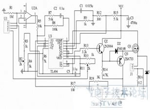
Figure 4 current driver schematic
2.3 Software Design
Figure 5 is a flow chart for completing a measurement and control:
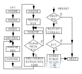
Figure 5 Ultrasonic inspection operation status flow chart
3, experimental test results
3.1 Resolution of measurement
At the temperature T=24.875 °C, the timing pulse data corresponding to each distance is shown in Table 1:
Table 1
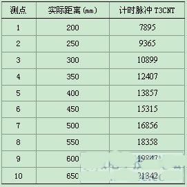
As can be seen from the data in the table, the count pulse has about 30 changes per 1 mm of the actual distance, and each count pulse is 0.1 μs.
3.2 Real-time response of the system
The time taken by the system for each cycle of measurement and control is mainly composed of two parts, that is, the time when the ultrasonic wave recognizes the operating state of the damper and the time when the current driver receives the control signal to the output current, the former is processed after three times of measurement. As the final counting pulse value, the maximum time for each measurement is about 2.5ms, a total of 7.5ms; Figure 6 is the measured dynamic response of the current driver under the step-up and falling signals, the above is the step input signal Curve, the amplitude of each vertical grid is 2.00V; the following is the measured response curve at both ends of the sampling resistor, the amplitude of each grid is 1.00V; the horizontal is the time axis, the width of each grid is 2.00ms; it can be seen Under the step signal excitation, the actual rise time and fall time are less than 2.5ms, so the total dynamic response time of the system is about 10 ms, which fully meets the real-time requirements.
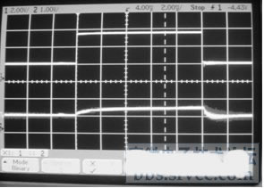
Figure 6 Dynamic response diagram of the current driver
3.3 System stability
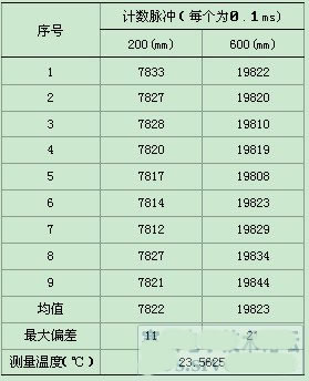
The stability of the system is mainly determined by the over-speed wave sensing and the current driver part. The former may cause false triggering due to environmental factors. Therefore, in a measurement and control cycle, the installation position and possible operation of the damper are combined by three consecutive measurement data. The maximum speed and other data validity analysis to determine the exact time of this cycle, Table 2 is the static measurement 9 times at the same distance:
Table 2
Since the inductance of the damper is about 2.45mH and the static resistance is about 1.2Ω. When the current driver adopts the BUCK conversion topology circuit structure, the current ripple of the output of the smoothing inductor and the filter capacitor is small, so the linear part behind the switch tube It is a typical first-order inertia link. After PI adjustment, its unit step response has no steady-state error, and there is no overshoot and peak time. As long as the feedback coefficient is suitable, the system is stable.
4 Conclusion
In this paper, ultrasonic sensor and digital signal processor are used to sense the operating state of magnetorheological fluid damper. The pulse width modulation (PWM) principle is combined with the impedance characteristics of magnetorheological fluid damper to design its current source driver. Software and hardware The design is simple and convenient, and it can meet the real-time and resolution requirements of the system. It also has certain reference value for similar non-contact dynamic displacement measurement systems.
references
[1] KJ Kitching, DJ Cole, and D. Cebon. The development of a heavy vehicle semi-active damper [J]. Proc. Intl.Symposium on Advanced Vehicle Control. AVEC'96, Aachen, German, 1996.
[2] Y. He and J. McPhee. A Design Methodology for Mechatronic Vehicles: Application of Multidisciplinary Optimization, Multibody Dynamics, and Genetic Algorithms [J]. submitted to Vehicle System Dynamics, 2004.
[3] Sung-Ryong Hong, Seung-Bok Choi. Vibration Control of a Structural System Using Magneto-Rheological Fluid Mount [J]. Journal of Intelligent Material Systems and Structures, Vol. 16(111-12), 2005.
[4] B. Cretin, P. Vairac, N. Jachez, , et al. Sensitive ultrasonic vibrometer for very low frequency applications[J].REVIEW OF SCIENTIFIC INSTRUMENTS 78, 085112 _2007.
[5] Hannes EImer, Herbert Schweinzer. High Resolution Ultrasonic Distance Measurement in Air Using Coded Signals [C]. IEEE Instrument and Measurement Technology Conference Anchorage, AK, USA, 21-23 2002.
[6] Zhao Wei, Xiang Wei, Wang Zhong. Development of high-accuracy ultrasonic range finder [J]. Sensor Technology, Vol. 22, No. 2, 2003, 55-57. Zhao Haiming,Bu Yingyong,Wang Jiwei.Study on a High Precision Ultrasonic Distance Measurement Method[J].Journal of Hunan University of Science and Technology(Natural Science Edition),2006,2006, Vol. 21, No.3 35-38.
We cover many types of Connectors for industrial, electrical and automotive, such as IP68 and waterproof connectors, OBD diagnostic connectors, also the standard or custom-designed power connectors for MINI FIT, MICRO FIT, MATE-N-LOCK.
Connectors System,Board System Connector,Efi System Injector Connector,Efi System Car Connector
ETOP WIREHARNESS LIMITED , https://www.etopwireharness.com