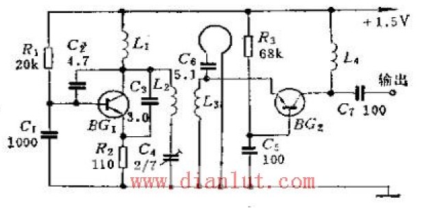
Transistor BG1 and C2, C3, C4, L2 and distributed capacitance constitute a modified crapper oscillator, L2 is the oscillating inductor, C4 is the frequency adjustment capacitor, and changing the size of C4 can achieve the purpose of changing the local oscillator frequency. BG2 is a mixing frequency oscillator. The oscillating signal is mixed by the L3 coupled to the emitter of BG2 and the UHF signal received by the antenna TX. The intermediate frequency obtained by the mixing is amplified by BG2 and output by C7. The mixing stage is a broadband output, which is good for converter stability. In the line, Ls also has a function of forming a high-pass filter with Cs to filter out interference from VHF band TV signals. Due to the inductive coupling method, as long as the distance between L2 and L3 is changed, the strength of the oscillating signal input to the BG2 emitter can be changed, so that the mixing tube works at an optimum state.
Sewing Machine Servo Motor,Dorna Servo Motor,Industrial Motor,Brushless Sewing Machine Motor
LISHUI SHUANGZHENG MOTOR CO.,LTD. , https://www.szservomotor.com