First of all, thanks to kai1103 and the great brother who designed the kimera make it easy to make the keyboard you want.
Secondly, thanks to the author of the LifeTyper blog, the use of the Kicad part is basically a reference to his tutorial
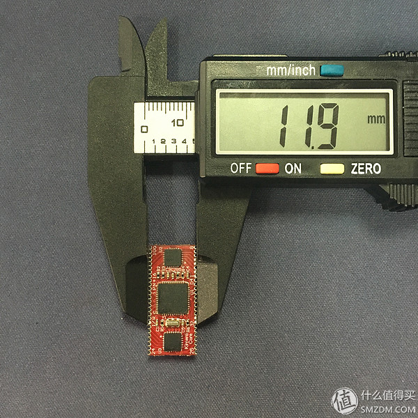
What is kimera coreIntroduce the introduction of the great brother:
The kimera core has the advantages of small size, high integration, easy secondary development, and simple firmware editing. It supports custom queues, four-lamp control, multiple lighting effects, firmware tools, and the same tkg-toolkit as the GH60. Using kimera core to make your own keyboard just needs to determine the position and matrix relationship of all the keys (because kimera core matrix rows and columns can be freely defined, so basically only need to insert the keys into the matrix).
 Kimera core's github link
The secondary development manual written by the big brother
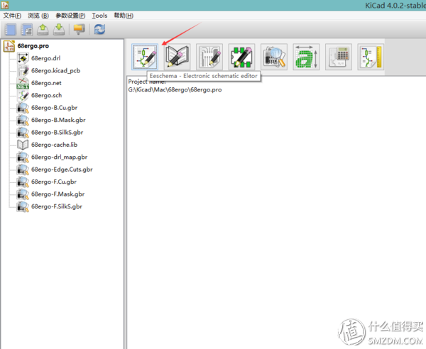
PCB design software neededOpen source PCB design software Kicad (download address)
Kicad tutorial
Online key design tool kle
AutoCAD: used to design the key coordinates of the specific coordinates and shell shape, etc.
Online firmware editing tool tkg
Firmware refresh tool tkg-toolkit (also from Kai Kai's hand)
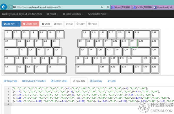
The first step, use kle to draw the layout of the key you want (layout, also called allocation)
Kle all graphical interface is very suitable for layout design, and can output raw code, used to generate firmware
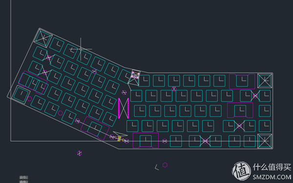
The second step is to use AutoCAD to draw the layout
You can draw small squares of various length keys first, and then arrange the small squares according to the design in kle. The distance between the keys and the keys can be calculated with n × 19.05mm.
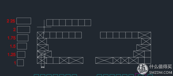
You can then deform the map, mark the center point of each axis, and create a coordinate system at the right place to position each key in kicad (if it is a normal keyboard, you can also use 19.05 directly Calculate button coordinates

The third step, according to the specification given by Cherry, is to draw the outline of the axis, satellite axis, etc. in kicad.
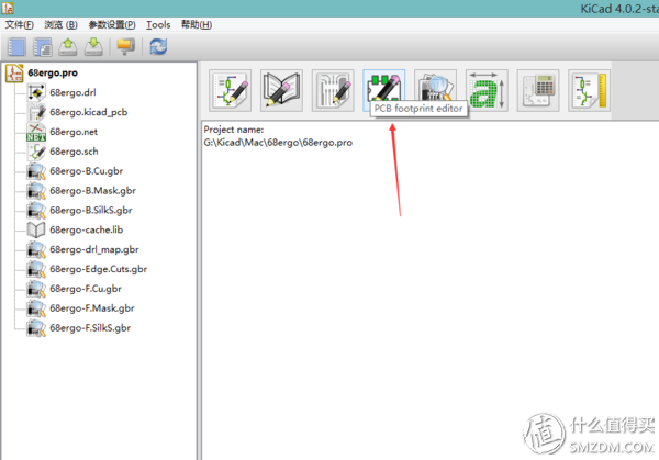
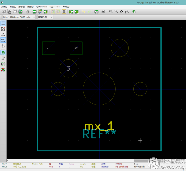
Because I am not a student of Koban, I’m directly involved in the process. I directly sealed the diodes and shafts into a single original.
Cherry's specification can refer to
The fourth step, according to the design of the queuing design drawing (mainly the key matrix)
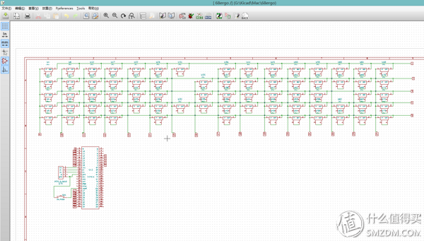
The way the wilderness is compared to the wild, so many of the originals' placements should not be in accordance with the specifications. Professionals should not spray me.
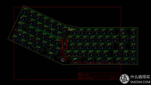
Step 5: Place the originals according to the key coordinates measured in AutoCAD
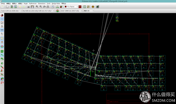
This describes the steps of skipping the original correspondence, generating netlists, and the original coordinate metrics. For details on related operations in kicad, refer to the tutorials above.
The sixth step, design the shell in Auto
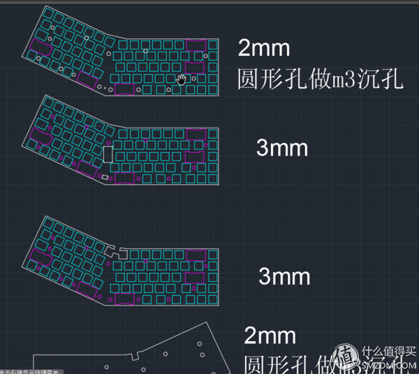
The reason why the shell is drawn in AutoCAD is because the hole and shape of the screw in the shell will influence the hole position in the PCB, and the hole position will affect the alignment. If the line is in the Kicad, the line will go well. Possible to cut off the line when adding screw holes and outer contours to pcb
Step 7, add pcb outline, screw holes, wiring in Kicad
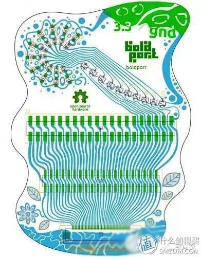
 Because the electrical requirements of the keyboard are not very high, the wiring just needs to follow the prompt in kicad to draw the white line that represents the need to connect. If you have a little bit of art bacteria, you can also try foreigners to use this kind of consciousness flow method.
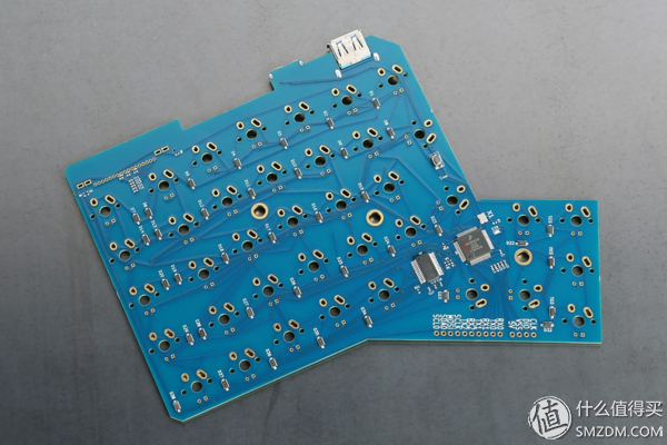


The eighth step, kicad export gerber file, kicad output shell drawings, Taobao find a shop custom
The operations in kicad basically follow the steps mentioned in the previous tutorial, and the screenshots are not illustrated here.
Pcb I was looking for Jiali Chuang, shell Taobao to find the acrylic processing, what is the copper column screw to find Taobao, the main control Kimera can play, w Oh, is to find a big brother to take
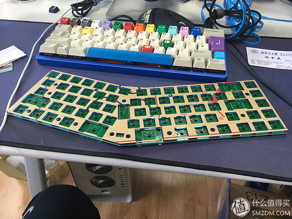
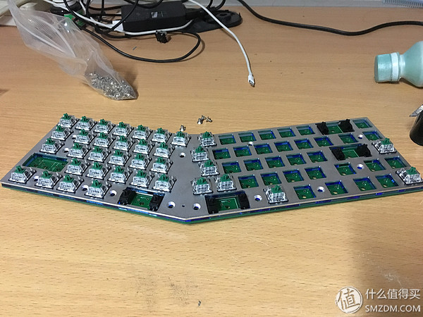
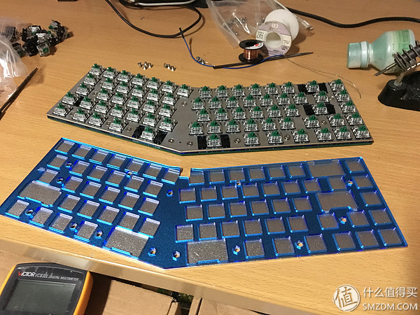
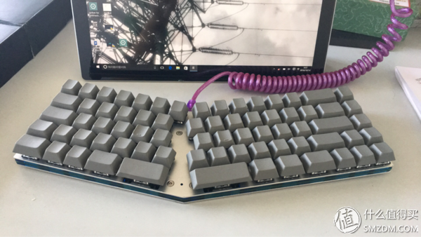
The ninth step, assembly


PCB 5 tablets 140 yuan
G green axis 1 yuan x 100 = 100 yuan (more after use)
Acrylic 85 yuan (I'm looking for this more expensive. But the color is much faster processing)
Screws, copper posts, satellite shafts, foot stickers and other accessories 0 yuan (40% of Golbat used)
Aluminum plate No money is being asked for processing under the line
Keycap: enjoypbt no moment 170 yuan (salted fish, then feel better to buy new)
Kimera core 100 yuan
A total of 600 yuan (actually a lot cheaper)
Layout reference code: